Book Appointment Now

Where the TU-872 SLK laminate fits: Dk 3.8 and Df 0.009 at 10 GHz, Tg 200 C, plus a loss-tier table and channel-loss rules for picking it.
TU-872 SLK Laminate: Dk, Df and M4 Selection Guide
The TU-872 SLK laminate is the grade most teams reach for when a standard FR-4 stackup runs out of loss budget but an ultra-low-loss platform is still hard to justify. It is a modified epoxy FR-4 system with a published Dk of 3.8 and a Df of 0.009 at 10 GHz, which puts it in the M4 mid-loss tier rather than in the PPO family. The engineering question is never whether it is good; it is whether your channel, your layer count and your reliability target actually need it.
This guide separates the three decisions buyers usually blur together: reading the datasheet correctly, placing the grade on the loss ladder, and knowing the channel conditions where stepping up a tier stops paying for itself. Numbers below come from the supplier datasheet and from the laminate table we work to on production orders, so you can map them straight onto a stackup review.
Table of Contents
- What the TU-872 SLK Laminate Actually Is
- TU-872 SLK Laminate Specs That Drive Design
- Where the M4 Mid-Loss Tier Sits on the Loss Ladder
- Turning Dk and Df into an Insertion Loss Budget
- TU-872 SLK Laminate vs the Ultra-Low-Loss Tier
- Hybrid Stackups That Mix Loss Tiers
- Thermal Reliability: Tg, Td and CAF Behaviour
- Process Compatibility: What Changes on the Floor
- Incoming Inspection Checklist for a Mid-Loss Core
- Applications Where This Grade Pays Off
- FAQ
- Have Your Stackup and Loss Budget Reviewed
What the TU-872 SLK Laminate Actually Is
The base resin is a high-performance modified epoxy, not a PPO or hydrocarbon system. Reinforcement is regular woven E-glass, and the resin is toughened with an allyl network forming compound, which is why the material holds up to drilling and to lead-free reflow without the brittle feel of early low-loss epoxies. The laminate is supplied as cores under the TU-872 SLK designation with TU-87P SLK prepreg, so both halves of the build come from the same qualified system.
That combination matters at the purchasing stage. Because the chemistry stays epoxy-based, a fab can run it on the same desmear line, the same lamination press family and the same drilling recipes it already uses for FR-4. You do not inherit a new process window, a new qualification cycle or a new scrap rate, which is the hidden cost most tier-step comparisons leave out.
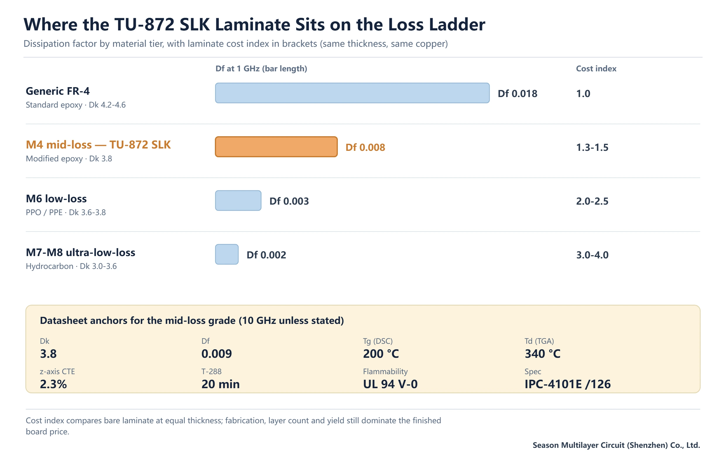
What you give up is the last few tenths of a dB. An epoxy system cannot reach the dissipation factor of a PPO or hydrocarbon platform, so the grade is a deliberate middle point: better than generic FR-4 by roughly a factor of two in Df, short of the ultra-low-loss class. If your link budget needs the PPO tier, no amount of process tuning on this material will get you there. The comparison is covered in more depth in our laminate selection guide.
TU-872 SLK Laminate Specs That Drive Design
The table below is the set of values worth writing into a stackup drawing. Electrical values are quoted at 10 GHz with 50% resin content, which is the condition the supplier publishes; thermal values follow the test method in the right-hand column, and mixing methods is the single most common source of arguments between a designer and a fabricator.
| Property | Typical value | Test method or note |
|---|---|---|
| Resin system | Modified epoxy, FR-4 type | Epoxy-based, lead-free process compatible |
| Reinforcement | Woven E-glass | 106, 1080, 3313 and 2116 styles available |
| Tg | 200 °C | DSC; 220 °C by DMA, 190 °C by TMA |
| Td (decomposition) | 340 °C | TGA, 5% weight loss |
| CTE, z-axis | 2.3% | 50–260 °C |
| T-260 / T-288 | 60 min / 20 min | With copper, no delamination |
| Dk | 3.8 | 10 GHz, 50% resin content |
| Df | 0.009 | 10 GHz, 50% resin content |
| Flammability | UL 94 V-0 | UL designation FR-4.0, file E189572 |
| Laminate spec | IPC-4101E /29, /99, /101, /126 | /126 listed on the QPL |
| Core thickness | 0.05–1.58 mm | Sheet or panel form |
| Copper foil | 1/3 to 5 oz | Built-up and double-sided |
Two numbers in that table get misread constantly. First, Tg appears three times with three values, and none of them is wrong; DSC, DMA and TMA measure different transitions. When a drawing says simply Tg 180 °C or above, ask which method, or you will reject a conforming lot. Second, T-288 is a delamination resistance figure, not a reflow profile limit. Twenty minutes at 288 °C is headroom, not a target.
The IPC-4101E slash sheets are worth keeping on the purchase order. Citing /126 (with its QPL listing) alongside the material name gives an inspector something to test against, and it separates a genuine TU-872 SLK core from a look-alike mid-loss grade sold under a similar name. The scope of the laminate specification series is described by the Global Electronics Association, and standard designations are summarised in our IPC standards overview.
The UL side is equally concrete: the designation is FR-4.0 under UL 746E with file E189572 and a 94 V-0 flame rating, and a maximum operating temperature of 130 °C appears on the yellow card. That operating temperature is a system-level rating, not a soldering limit, and it is frequently confused with Tg. Lookup of a supplier file number is done through UL Solutions; a laminate certificate that cannot be traced to a file number should be treated as unverified.
Where the M4 Mid-Loss Tier Sits on the Loss Ladder
Fabs and material engineers sort laminates into loss tiers, and the tier label is far more useful in a design review than a brand name. The ladder below uses the dissipation factor bands we work to, with cost expressed as an index against a generic FR-4 core of the same thickness. Cost moves in steps, so the jump from M4 to M6 is a bigger commercial decision than the jump from generic FR-4 to M4.
| Tier | Typical Df (1 GHz) | Resin family | Typical channel use | Laminate cost index |
|---|---|---|---|---|
| Generic FR-4 | 0.015–0.020 | Standard epoxy | Short routes, lower data rates, cost-led builds | 1.0 |
| M4 mid-loss | 0.008 | Modified epoxy | Mid-length high-speed channels, servers, telecom line cards | 1.3–1.5 |
| M6 low-loss | 0.002–0.0034 | PPO / PPE / modified PPO | Backplanes, long reach, higher lane rates | 2.0–2.5 |
| M7 to M8 ultra-low-loss | 0.0005–0.002 | Hydrocarbon, PPE blends | Longest channels, tightest eye masks | 3.0–4.0 |
Read the index column with care. Laminate is a minority of the finished board price on a 10-layer build; fabrication, yield and layer count dominate. That is why a 1.4 index on the core often lands as a much smaller percentage on the quotation, and why teams sometimes over-specify the laminate while under-specifying the things that actually sink yield, such as impedance tolerance and registration.
The other reason to place the grade on a ladder rather than on a datasheet is that Df alone does not predict a channel. A well-designed M4 stackup with a continuous reference plane and controlled impedance routinely beats a poorly executed ultra-low-loss build. When a design fails at corner, the first question should be about return path and via stubs, not about the resin.
Turning Dk and Df into an Insertion Loss Budget
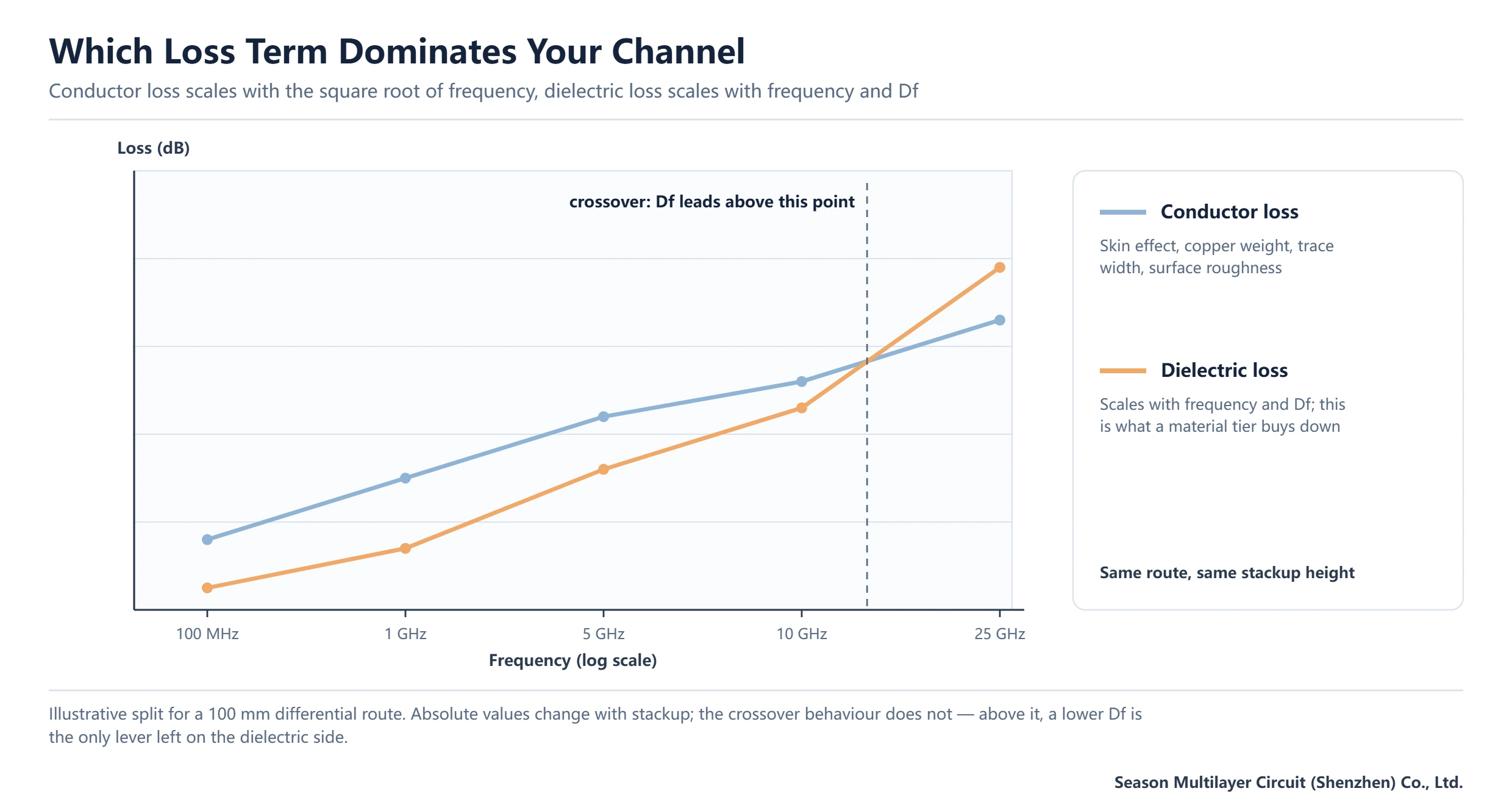
Insertion loss on a long trace splits into conductor loss and dielectric loss. Conductor loss scales with frequency and with the square root of frequency through skin effect; dielectric loss scales close to linearly with frequency and directly with Df. The practical consequence is that at a few hundred megahertz the copper dominates, and by 10 GHz the dielectric term is often the larger half on a long route. That crossover is exactly where a Df of 0.009 instead of 0.019 starts to matter.
Dk plays a different role. It sets the trace width a given impedance needs, so a 3.8 Dk material pulls traces narrower than a 4.3 Dk FR-4 for the same target impedance and dielectric height. Narrower traces mean slightly higher conductor loss and a tighter etch tolerance, which is why impedance tolerance has to be agreed before the artwork is released. We hold ±10% as standard, with ±8% and ±5% available on request for tighter channels; the measurement methods behind those numbers are covered in our impedance measurement guide.
A workable budgeting method, in the order that resolves arguments fastest: fix the lane rate and the longest route; get the loss per inch from the material datasheet at the fundamental frequency; add connector and via contributions; compare the total with the channel spec at the worst-case temperature. If the margin is thin, either shorten the route or step up a material tier. If the margin is comfortable, M4 is the right answer and the extra tier is waste.
TU-872 SLK Laminate vs the Ultra-Low-Loss Tier
Against the PPO family, the honest summary is that the TU-872 SLK laminate loses about 0.006 in Df and gains process familiarity, wider thickness availability and a shorter material lead time. On a 100 mm route at 10 GHz that difference is a measurable fraction of a dB; on a 500 mm backplane it can be the whole margin. Length, not prestige, decides the tier.
For reference, TU-883 sits in the M6 band with a Df of 0.003 on a PPO system, and its selection logic is a useful mirror: it makes sense when the channel is long or the lane rate is high enough that a 0.006 Df improvement buys real eye height. The trade-off table in our TU-883 selection guide reads the same way in reverse.
A decision rule that survives contact with production: if the channel passes with at least 2 to 3 dB of margin on M4 across temperature and lot variation, stay on M4. If margin sits inside 1 dB at the corner, the extra tier is cheaper than a respin. If the design fails on M4 by a wide margin, check the stackup and the via structure before buying a more expensive core, because a material change rarely fixes a return-path problem.
Hybrid Stackups That Mix Loss Tiers
Not every layer deserves the same dielectric. A common and cost-effective arrangement puts the mid-loss cores where the high-speed routing lives, keeps power and ground layers on standard FR-4, and controls the impedance of the critical layers only. The result is a stackup that behaves like a mid-loss board on the channels that matter without paying the tier premium on all of them.
Hybrid builds bring their own risks and they are all mechanical. Different resin systems have different CTE and different cure shrinkage, so the stackup has to stay symmetric in thickness and copper distribution or the panel will bow during reflow. Press parameters need a compromise profile, and the prepreg resin must be compatible with the cores it bonds. We plan hybrid builds from 2 to 30 layers and confirm the lamination window at engineering review rather than assuming the standard cycle.
Documentation is where hybrid projects fail quietly. Each layer needs its material named, its Dk tied to the impedance target, and the prepreg style and resin content stated. A stackup drawing that says only “high-speed material” on four layers cannot be built repeatably and cannot be inspected. Our stackup design rules cover the symmetry and copper-balance side of this in more detail.
Thermal Reliability: Tg, Td and CAF Behaviour
A 200 °C glass transition temperature is comfortable for lead-free assembly. Reflow peaks land near 245 to 260 °C at the board surface for under a minute, and what matters is not the peak but the number of excursions the laminate survives without delamination or measurable shift in z-axis expansion. The 340 °C decomposition temperature and the 60 minute T-260 result give the margin that multilayer boards with several press cycles need.
The 2.3% z-axis CTE figure does real work on thick boards. Barrel stress in a plated through hole is driven by how much the dielectric expands against the copper during thermal cycling; a lower expansion coefficient on a 2.0 mm board with a high aspect ratio is the difference between passing and failing thermal cycling. This is one place where a mid-loss core can outperform a cheaper standard FR-4 even before electrical arguments start.
CAF resistance is the other reliability dimension and it is the one procurement teams ask about least. Ion migration between plated holes at voltage bias under humidity is a spacing-and-material problem, and the datasheet position of this grade is anti-CAF. For designs with tight hole-to-hole spacing and a bias above a few tens of volts, ask for the CAF test data on the actual lot rather than accepting a catalogue claim; our incoming laminate inspection process captures it on the material record.
Process Compatibility: What Changes on the Floor
Because the chemistry is epoxy, the fabrication route is largely unchanged: same inner-layer imaging, same desmear chemistry family, same plating line, same surface finishes. Three parameters do move, and they are worth stating in the fabrication note. The press cycle needs the supplier’s recommended profile rather than the generic FR-4 one, the drill parameters benefit from a fresh bit budget because the toughened resin is less forgiving of worn tools, and the etch compensation needs to account for the narrower trace widths that a 3.8 Dk implies.
Available cores run 0.05 mm to 1.58 mm with 1/3 oz to 5 oz copper, which covers most high-speed digital stackups without forcing a build-up. If your design needs thinner dielectric between the high-speed layers, the prepreg side of the system does the work, using 106, 1080, 3313 or 2116 glass styles. Combining a thin core with heavy copper is where warpage risk climbs, and that is a conversation to have at stackup review rather than after the first panel.
One practical DFM point: narrow traces and tight spacing shift the defect spectrum. Opens and mouse bites become more likely than shorts, so AOI recipes and electrical test thresholds should be revisited when a design moves from standard FR-4 to this grade. Gerber data conventions for those layers are defined by Ucamco, and it is worth confirming that the fabrication drawing carries the material callout in the same revision as the artwork.
Incoming Inspection Checklist for a Mid-Loss Core
Laminate is the one input you cannot fix downstream. A mid-loss core delivered with a Dk 0.2 off nominal will show up as an impedance failure three process steps later, after the panels are already drilled. The checklist below is the one we apply to incoming material on high-speed orders, and it is short enough to run on every lot.
| Check | Method | Acceptance |
|---|---|---|
| Material identity | Label, IPC-4101E slash sheet, UL file on the shipping document | Matches the purchase order and the stackup drawing |
| Dk and Df | Supplier lot data, or coupon measurement on first article | Within the datasheet tolerance; flag any shift before release |
| Tg | DSC on a sample when the lot is new or the supplier changes | Meets the drawing value with the stated method |
| Delamination resistance | T-288 or T-260 on a test coupon | No measurable delamination within the stated time |
| Thickness and copper | Micrometer at nine points, foil weight check | Inside the core tolerance band for the impedance model |
| Warp and twist | Flat-plate measurement after bake | Within the agreed limit for the panel size |
| CAF data | Supplier report on the same construction family | Available for high-voltage or fine-pitch designs |
Two failure modes are worth naming. First, a substitute grade with a similar Df but a different Dk: the impedance coupons shift and nobody notices until final test. Second, a core from a different press batch with a different resin content, which moves Dk by enough to break a 5% tolerance. Both are caught by measuring, neither is caught by reading a certificate.
Applications Where This Grade Pays Off
The natural homes are telecom and data infrastructure boards: base station units, line cards, server and storage motherboards, routers and backplanes, plus high-performance computing boards where the channel length is moderate and the layer count is high. In those builds the electrical requirement is real but not extreme, and the process familiarity of an epoxy system keeps yield predictable across 10 to 16 layers.
Concrete examples from our own production: 12-layer high-speed backplanes where long routes and connector launches dominate the loss budget, 14-layer computing boards with dense differential routing, and 6-layer optical module boards where the dielectric loss is secondary to layout discipline but the impedance target is tight.
Where it is the wrong call: boards that are cost-led with short routes and no impedance requirement, where standard FR-4 already passes; and boards at the opposite end, where the channel is long enough that only a PPO or hydrocarbon platform closes the eye. Both mistakes cost money, one through over-specification and the other through a respin.
Frequently Asked Questions
What is the TU-872 SLK laminate?
It is a modified epoxy FR-4 laminate reinforced with woven E-glass and toughened with an allyl network forming compound. Cores are designated TU-872 SLK and the matching prepreg is TU-87P SLK. It is designed for high-speed, low-loss multilayer work and it stays compatible with standard FR-4 fabrication processes, which is why it is usually classified as an M4 mid-loss material rather than an ultra-low-loss platform.
What are the Dk and Df of TU-872 SLK at 10 GHz?
The supplier publishes a Dk of 3.8 and a Df of 0.009 at 10 GHz with 50% resin content. Treat those as typical values at that frequency, not as constants: Dk falls slowly as frequency rises, and both numbers move with resin content and glass style. For an impedance model, always use the value that matches the frequency band and the prepreg build you are actually specifying.
Is TU-872 SLK halogen-free?
No. It is a brominated modified epoxy system with a UL designation of FR-4.0, so it should not be presented as halogen-free. If your compliance requirement is a material free of halogen, antimony and red phosphorus, specify our S1150G grade instead, which is the halogen-free laminate we keep in the standard portfolio with Tg of at least 150 °C.
What glass transition temperature does this laminate have?
200 °C by DSC, 220 °C by DMA and 190 °C by TMA. All three are correct for the same material because the methods detect different transitions. When a drawing or a purchase order states a Tg requirement, name the test method next to the number, otherwise a conforming lot can be rejected on a measurement difference rather than a material difference.
Can it be processed on a standard FR-4 line?
Yes. Imaging, desmear, plating and surface finish are unchanged because the resin is epoxy-based. The press profile should follow the supplier recommendation rather than a generic FR-4 cycle, drill bits should be changed on a tighter budget, and etch compensation should account for the narrower traces a 3.8 Dk implies at a given impedance. None of that requires new equipment.
When should I step up from an M4 mid-loss laminate to a PPO material?
Step up when the channel still fails or sits inside about 1 dB of margin at the corner on M4 across temperature and lot variation. If the design holds 2 to 3 dB of margin, the extra tier is waste. If it fails by a wide margin, review the reference plane continuity and via stubs first, because a more expensive core rarely rescues a return-path problem.
Can you build a hybrid stackup with this core and a low-loss prepreg?
Yes. Hybrid builds are common: mid-loss cores on the high-speed layers, standard FR-4 on power and ground, with impedance controlled only where the design needs it. The constraints are mechanical rather than electrical, so the stackup must stay symmetric in thickness and copper distribution, and the press profile has to be agreed at engineering review. We plan these builds from 2 to 30 layers.
Have Your Stackup and Loss Budget Reviewed
Send the stackup drawing, the target impedance and the longest route on the board. We will confirm whether an M4 mid-loss core closes the channel or whether the design needs the next tier, and we will say so before you commit to material.
Review covers layer symmetry, dielectric thickness against the impedance model, prepreg availability in the glass styles you need, and the process notes that keep a mid-loss build repeatable. Start with a stackup and quote request or read the wider PCB materials and laminates guide for the surrounding tier logic.