Book Appointment Now

How NPTH and PTH holes differ in tolerance, cost and inspection, and how to call out plated and non-plated slots so the drill floor builds the hole you drew.
NPTH and PTH Holes: Types, Tolerances and Fab Drawing Callouts
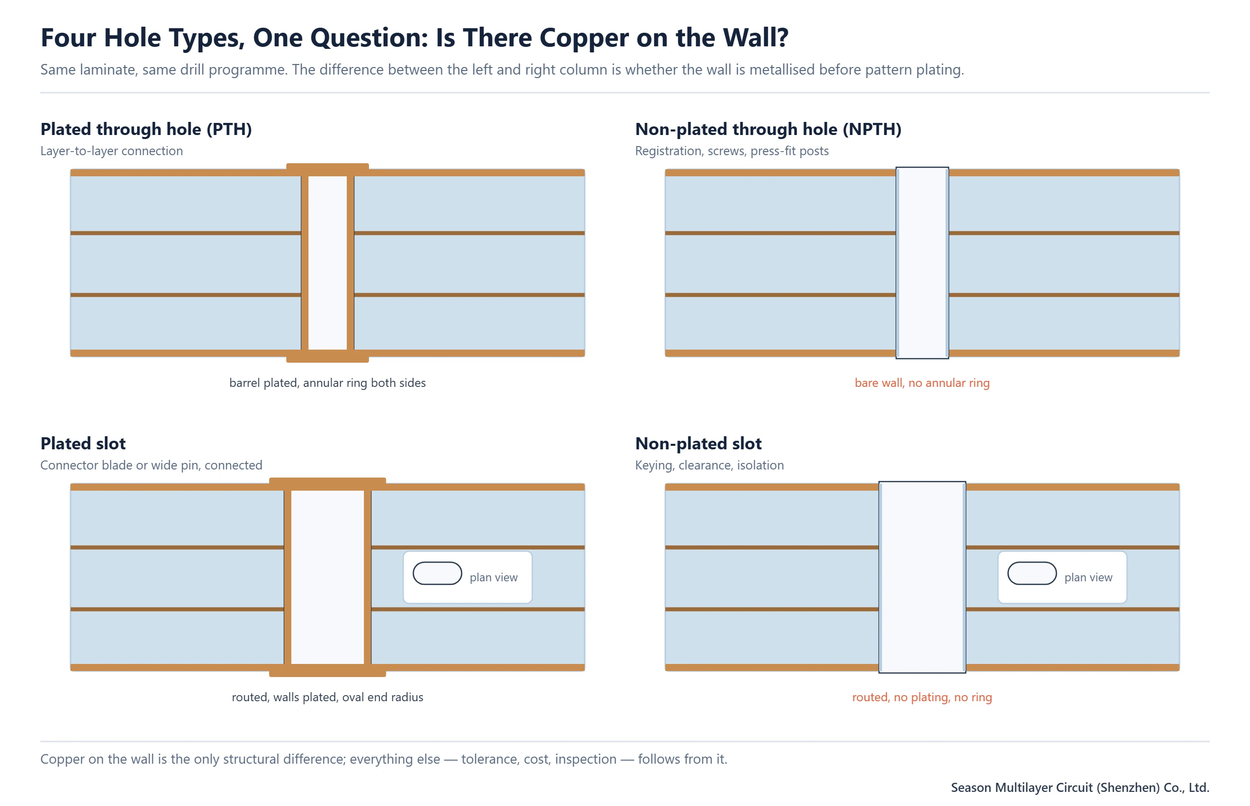
Almost every hole argument on a PCB order comes down to a single question that the drawing either answers or leaves open: is there copper on the wall? Once that is settled, everything else follows — the tolerance the shop can hold, whether the hole needs protection through plating, how it is inspected, and what it does to the price. This guide covers NPTH and PTH holes side by side, then extends the same logic to slots and cut-outs, which are routed rather than drilled and therefore obey a different set of limits.
It is written for the person who signs the fabrication drawing. The failure mode this page is meant to prevent is not a technical misunderstanding; it is a drawing that says one thing, a drill file that says another, and a shop that builds whichever one its CAM operator read first. Those boards arrive with the holes in the right place and the wrong plating, and nobody finds out until first article.
Table of Contents
- The One Difference That Decides Everything
- NPTH and PTH Holes: What Each Type Is For
- Why NPTH Holds a Tighter Tolerance Than PTH
- Slots: Routed Openings That Follow Router Rules
- How to Call Out NPTH and PTH Holes on a Fab Drawing
- Drill Charts, Excellon Files and the Plated Split
- The Five DFM Errors That Reach the Drill Floor
- Inspection: What Actually Gets Measured
- Cost and Schedule: What Actually Moves the Quote
- FAQ
- Send the Drill Data and the Drawing Together
The One Difference That Decides Everything
A drilled hole is a cylinder through laminate. A plated hole is that same cylinder with a metal film bonded to the wall and connected to the copper layers it passes through. The drill programme is identical; the difference is whether the panel goes through desmear and metallisation with that hole protected or open. Everything downstream — tolerance, cost, inspection method, thermal behaviour — is a consequence of that single decision.
This is why the classification has to live in the drill data and not only in a note. When the file carries both plated and non-plated tools in one list, CAM has to infer intent from whether a pad exists, and inference is where mistakes enter. A hole in a copper-free area is obviously non-plated; a hole with an annular ring that the designer intended as a mechanical spacer is not, and that is the case that reaches the drill floor wrong.
NPTH and PTH Holes: What Each Type Is For
PTH holes exist to connect. They are drilled, desmeared, metallised and pattern-plated so that the barrel links every copper layer it crosses, and they carry the current and the return path for the board. Their wall copper is specified rather than incidental: 18–30 µm of plated copper is the normal range, which lines up with IPC-6012 Class 2 at 20 µm average and 18 µm minimum, and Class 3 at 25 µm average and 20 µm minimum.
NPTH holes exist to hold, locate or clear. Screw holes, connector registration pins, mounting bosses and isolation clearances all fall here. No annular ring, no wall copper, and in most designs no electrical function at all. The subtlety is that a non-plated hole still has to survive the plating line without being plated, which means one of four methods: tenting the hole with dry film, plugging it with a resist plug before plating, drilling it after plating, or punching it during profile. Each has a cost and a positional consequence, and the fabricator picks based on hole size and quantity.
| Feature | Wall copper | Primary purpose | How it is produced | Cost effect |
|---|---|---|---|---|
| PTH, round | 18–30 µm plated | Layer-to-layer connection | Drill, desmear, metallise, pattern plate | Baseline; the cheapest connection on the board |
| NPTH, round | None | Mounting, registration, clearance | Drill with the hole protected, or drill after plating | One extra protection or drilling step |
| Plated slot | Plated on the walls | Wide pin or blade connection | Routed, then metallised | Routing set-up on top of plating |
| Non-plated slot | None | Keying, isolation, clearance | Routed, no plating | Routing set-up, no plating cost |
Why NPTH Holds a Tighter Tolerance Than PTH
Counter-intuitive but consistent across every shop: the hole with no plating is the hole with the tighter tolerance. A non-plated hole is typically held at ±0.05 mm and a plated hole at ±0.075 mm. The reason is arithmetic, not skill. Plating adds 20–25 µm of copper to each wall, so the finished plated hole is the drill diameter minus twice the plating thickness, and two walls of variable thickness double the uncertainty. The non-plated hole is the drill diameter, full stop.
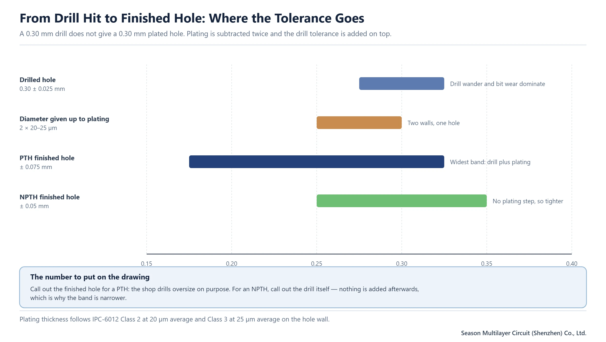
The practical instruction follows directly: call out the finished hole for a PTH and let the shop drill oversize, but call out the drill itself for an NPTH because nothing is added afterwards. Getting this backwards is a classic first-article failure — a 0.30 mm callout built as a 0.30 mm drill becomes a 0.25 mm plated hole, and the connector that was specified for a 0.30 mm pin no longer fits.
Press-fit connectors deserve their own line in the drawing. The compliant pin needs a controlled interference fit, which puts both the hole diameter and the positional tolerance inside a narrower window than a soldered through-hole, typically ±0.05 mm on diameter with a position control that matches. If a press-fit connector is on the BOM, say so on the fabrication drawing; a shop that assumes a soldered through-hole will drill to the wider standard band and the pins will not hold retention force.
Slots: Routed Openings That Follow Router Rules
A slot is not a stretched hole. It is a routed opening, which means the tool is a router bit of fixed diameter and the shape it can produce is the shape of that bit’s path. Two consequences follow immediately. The minimum slot width equals the bit diameter, and every internal corner inherits the bit radius, so a slot drawn with square ends will be built with rounded ones whether or not the drawing says so. In Chinese-language fab notes the slot is sometimes written SOLT; it means the same feature.
Both variants exist and they behave differently in the stackup. A plated slot is routed before plating so the walls take copper, which makes it an electrical connection for a wide blade or a connector tongue; it needs annular copper at both ends to connect to. A non-plated slot is routed and left bare, which makes it a keying feature, an isolation gap between two nets on the same layer, or a mechanical clearance around a PostScript-style standoff that must not short to anything.
| Opening | Made by | What limits the size | What it does to the order |
|---|---|---|---|
| Round PTH | NC drill, then metallisation | Bit diameter and hole aspect ratio | Nothing extra; scales below 0.2 mm where routing cannot |
| Round NPTH | NC drill with protection, or drill after plating | Bit diameter plus wall clearance to copper | A protection or second drilling step |
| Slot, plated or not | NC routing | Router bit diameter sets the minimum width | A separate routing set-up; oval ends are free, square corners are not |
| Rectangular cut-out | Two or more routed passes | Internal corner radius equals the bit radius | The most expensive opening per millimetre of perimeter |
Width is the number to check before release. Slots of about 1.0 mm and wider route cleanly with a standard bit; narrower slots are usually produced by stepping a drill along the path, which works but needs to be quoted as a review item rather than assumed. Slots also need a web of material between the opening and the board edge — under about 0.5 mm the edge starts to break out during routing, and a broken edge is a scrap panel.
How to Call Out NPTH and PTH Holes on a Fab Drawing
A fabrication drawing that will be built correctly the first time carries five things for its holes, and all five are cheap to produce at design time. The first is a drill chart that separates plated from non-plated tools with distinct symbols and distinct tolerances. The second is a finished-versus-drill statement for each tool: which dimension is the specified one. The third is the plating thickness requirement with the IPC class named. The fourth is the positional tolerance, referenced to datums rather than to the board outline. The fifth is a note on any hole that must stay clear of copper, because the negative space around an NPTH is as important as the hole itself.
- Split the drill chart into plated and non-plated sections, with a different symbol per tool and the count for each.
- State, per tool, whether the quoted diameter is the drill or the finished hole.
- Name the IPC class for wall copper rather than quoting a bare micrometre figure.
- Reference hole position to datums, and give the same tolerance in the chart and in the notes.
- Flag press-fit holes, and flag any NPTH that sits inside a copper pour.
- Describe slots by width, length, end condition and plating status — four numbers, one line.
The reason to spend effort here is that the drawing and the drill file can disagree silently. CAM reads the file, the operator reads the drawing, and when they conflict the shop builds what the file says. A note that contradicts the data is worse than no note at all, because it creates the impression that someone checked.
Drill Charts, Excellon Files and the Plated Split
Most boards are transferred as Excellon drill data plus Gerber images, and the cleanliness of that handoff decides how much of the drawing is actually read. Two files — one for plated tools and one for non-plated — remove the ambiguity entirely and cost nothing to produce, because the NPTH and PTH split is then a property of the data rather than an inference. A single combined file is workable when the tool list is annotated, but it relies on CAM correctly inferring intent from the copper artwork, and that inference is where the errors live.
The Gerber side matters for slots, because a routed opening is a profile feature rather than a drill hit. Slots belong on a rout or profile layer with a clear note, or as a milled path in the drill data if the shop accepts it. Modern Gerber X2 carries attributes that can label a feature as plated or non-plated in the file itself, which closes the gap between drawing and data; the format specification is maintained by Ucamco, and the attribute set is worth adopting if the CAD tool supports it.
One more file-level habit pays for itself: include the layer count and the finished thickness in the drill data header, not only on the drawing. Drill depth, hit count and aspect ratio are all computed from those two numbers, and a mismatch between the header and the drawing is exactly the kind of thing that gets noticed after the first panel.
The Five DFM Errors That Reach the Drill Floor
These are not theoretical. They are the five that recur across incoming data packages, and each one has a simple check that takes less time than the re-quote it prevents.
| Error | What the shop sees | Consequence | Fix |
|---|---|---|---|
| NPTH drawn with an annular ring | Ambiguous intent, plated or not | Hole plated that should be clear, or vice versa | Remove the ring or mark the tool non-plated explicitly |
| Slot narrower than the router bit | Feature cannot be routed as drawn | Shop widens it silently and the part no longer fits | Draw at achievable width, or accept a stepped-drill note |
| Square internal corner | Tool radius larger than the drawn corner | Corner clipped, sometimes into a trace | Add the radius the bit will produce |
| Hole too close to the board edge | Less than 0.5 mm of web | Break-out during routing, scrapped panel | Move the hole or accept a routed notch instead |
| Copper pour over an NPTH | Plating protection cannot hold | Copper ring grows around a hole that must be clear | Keep the pour back by at least the hole radius plus clearance |
The fourth and fifth items are worth a second look because they are the ones that survive a design review. A pour that overlaps a non-plated hole looks like a connection in the viewer and builds like a short between a screw head and a net. The clearance rule is simple: keep copper back from the hole edge by at least the plating-protection tolerance, and state the requirement in a note so that it survives a copper re-pour later in the project.
Inspection: What Actually Gets Measured
Hole quality is verified in three different ways, and it is worth knowing which one covers which claim. For both NPTH and PTH, diameter and position are checked optically or with a coordinate measuring machine on the finished panel, and that is what confirms the tolerance band. Wall copper is checked by microsection: a coupon is potted, ground, polished and measured, and that is the only method that actually proves the 20 or 25 µm average. Thermal stress is checked by a solder float at 288 °C followed by a second microsection to look for barrel cracks and delamination.
The microsection is also where non-plated holes get caught if the protection failed. A wall that should be bare and shows a thin metallic film will not fail electrically in a simple continuity test, because there is nothing to test against — it shows up as a plating nodule on the section, or as a short discovered months later when a mounting screw grounds a net that was supposed to float.
For aspect ratios at the edge of the process, the inspection plan matters more than the specification. A 12:1 hole gets adequate exchange of chemistry in desmear and plating; at 20:1 the wall quality depends on agitation and on the shop’s own qualifying data, and the honest answer is that it should be reviewed rather than assumed. The aspect ratio and plating limits guide covers the mechanism, and the electroless copper process explains what has to happen on the wall before pattern plating can build on it.
Cost and Schedule: What Actually Moves the Quote
Hole cost is not driven by the number of holes; it is driven by the number of operations the hole adds. A plated round hole is the baseline: drill, desmear, metallise, plate, and it is all part of the standard flow. A non-plated hole in the same panel adds a protection step or a second drilling pass, which is a set-up rather than a per-hole charge. A slot adds a routing set-up. A cut-out adds multiple routed passes and, usually, a conversation about corner radii.
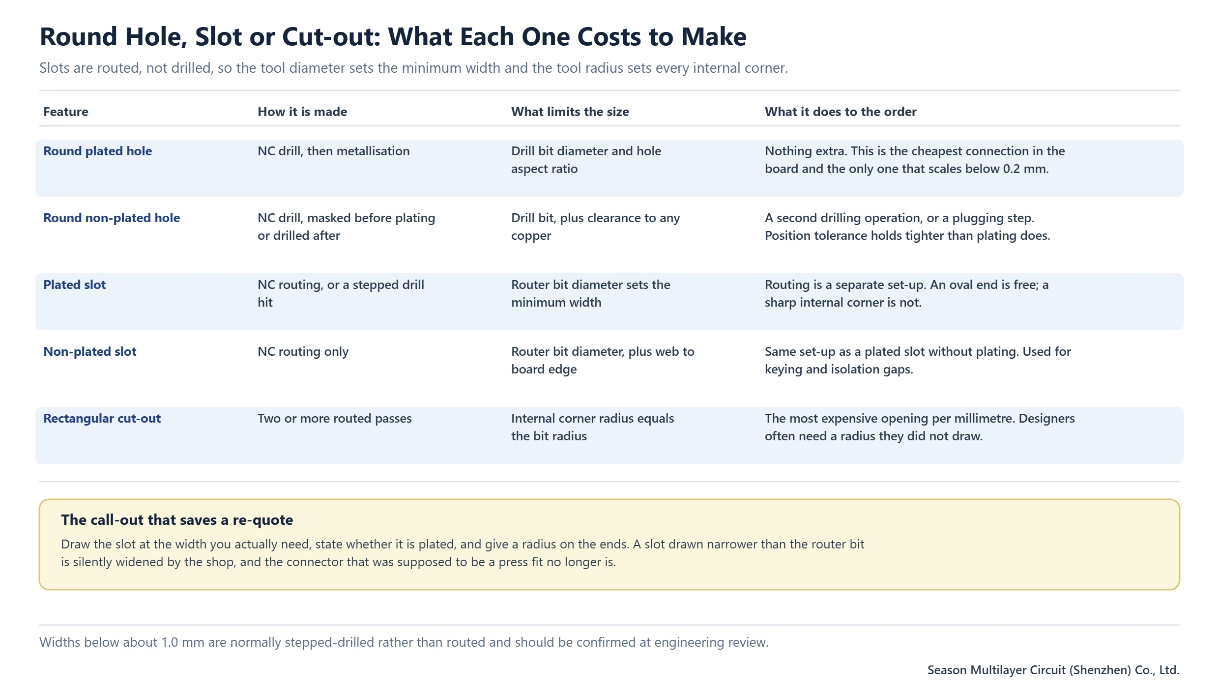
That structure is why two boards with the same hole count can quote very differently, and why the useful question at quotation is not how many holes but how many distinct hole types and rout features the panel contains. A panel with four NPTH and PTH tool sizes and one slot width is a different order from one with eleven of each. Consolidating tool sizes reduces set-ups; consolidating slot widths to one router bit removes a set-up as well. Neither change touches the design electrically, and both are visible in the price.
The via protection comparison is the other half of the same conversation, because whether a via is tented, plugged or left open changes both the plating flow and the surface finish decision. And on HDI builds the rules shift again, since laser-formed blind vias at 0.1 mm diameter follow different limits from mechanical drills; the HDI versus standard PCB comparison sets out where that boundary sits.
Frequently Asked Questions
What is the difference between NPTH and PTH holes?
A PTH has copper plated on the hole wall and connects the copper layers it passes through. An NPTH has a bare laminate wall with no plating and no annular ring, and is used for mounting, registration or clearance. The drill programme can be identical; the difference is whether the hole is protected during metallisation, which is why the callout has to be explicit.
Why is the tolerance on an NPTH tighter than on a PTH?
Because plating adds thickness. A plated hole finishes at the drill diameter minus twice the wall thickness, so 20–25 µm of copper per wall plus its variation widens the result to about ±0.075 mm. A non-plated hole finishes at the drill diameter with no addition, which allows roughly ±0.05 mm. The tighter band is arithmetic, not extra skill.
Should I call out the drill size or the finished hole size?
Finished size for a plated hole, and the drill itself for a non-plated hole. If you call out 0.30 mm on a PTH and the shop drills 0.30 mm, plating brings the finished hole down to about 0.25 mm and the pin no longer fits. State which dimension is authoritative for every tool in the drill chart.
How much copper is on a plated through-hole wall?
The normal range is 18–30 µm. That corresponds to IPC-6012 Class 2, which calls for 20 µm average and 18 µm minimum, and Class 3, which calls for 25 µm average and 20 µm minimum. Naming the class on the drawing is more useful than quoting a single figure, because it tells the shop which acceptance table applies at inspection.
Can a slotted hole be plated?
Yes. A plated slot is routed before metallisation so the walls take copper, and it is used as an electrical connection for a wide blade or connector tongue, with annular copper at both ends. A non-plated slot is routed and left bare, and is used for keying, isolation gaps or mechanical clearance. Both are routed, so the router bit diameter sets the minimum width either way.
What is the narrowest slot a fabricator will route?
About 1.0 mm is the practical routing floor, because the slot cannot be narrower than the router bit. Narrower slots are usually produced by stepping a drill along the path rather than routing, which is a different operation and should be confirmed at engineering review instead of assumed. Slots also need roughly 0.5 mm of material between the opening and the board edge to avoid break-out.
Do non-plated holes need a keep-out on copper layers?
Yes. Copper pour that overlaps an NPTH looks like a connection in the CAD viewer and builds like a short between a screw head and a net, because the plating protection cannot hold where there is copper to plate against. Keep copper back from the hole edge by at least the protection tolerance, and put the requirement in a note so a later re-pour does not undo it.
Send the Drill Data and the Drawing Together
Upload the Gerber data, the Excellon drill files with the NPTH and PTH tools separated, and the fabrication drawing. Engineering will cross-check the two against each other before release and flag any hole, slot or cut-out whose callout cannot be built as drawn — the failures that are cheapest to find at data review rather than at first article. Multilayer builds from 2 to 30 layers are supported in volume, with sample quantities up to 64 layers reviewed case by case.
The manufacturing services overview covers how drilling, plating and routing are sequenced, and the HDI technology reference covers where microvia rules replace mechanical drill rules.