Book Appointment Now

S1000-2M laminate values, real limits and where the grade stops working: Tg 180, Td 355, Z-axis CTE, Dk 4.6 and Df 0.018, plus a grade ladder and press window.
S1000-2M Laminate: Tg 180 FR-4 Grade Selection, Stackup and Limits
A S1000-2M laminate is the grade that shows up when a stackup needs more thermal margin than a general-purpose FR-4 allows but cannot justify a low-loss material. It is a woven-glass epoxy with a Tg of 180 °C by DSC, a decomposition temperature of 355 °C and a Z-axis expansion of 2.4% between 50 and 260 °C. Those three numbers, rather than any adjective in the brochure, decide whether a board survives a lead-free assembly line and years of field cycling.
This guide reads the data the way a fabricator and a buyer actually use it: which values are typical rather than guaranteed, what Tg and Td do and do not promise, where Dk 4.6 and Df 0.018 stop being good enough, how the grade sits against S1170G and S1150G, and what to write on the purchase documents so the material that arrives matches the material that was qualified. It ends with the cases where this grade is the wrong call, which are easier to recognise than most buyers expect.
Table of Contents
- What the S1000-2M Laminate Grade Actually Is
- Reading the S1000-2M Laminate Datasheet Without Guessing
- Tg 180 and Td 355: What the Numbers Do and Do Not Promise
- Z-Axis CTE and Through-Hole Reliability: The Real Selection Driver
- Dk 4.6 and Df 0.018: Where This Material Still Works
- S1000-2M vs S1170G vs S1150G: Choosing on the Ladder
- CTI PLC 3 and Creepage: The Line Buyers Skip
- Processing the S1000-2M Laminate in a Production Shop
- When the S1000-2M Laminate Is the Wrong Call
- What to Put on the Fabrication and Purchase Documents
- FAQ
- Have the Stackup and Material Call Checked Before Release
What the S1000-2M Laminate Grade Actually Is
S1000-2M is a Shengyi Technology laminate built on woven E-glass with an epoxy resin system, supplied with S1000-2MB prepreg as its matching bonding sheet. Its UL / ANSI designation is FR-4.0 and its reference specification sheet is IPC-4101/126, which is the IPC slash sheet a specifier should quote rather than a trade name alone. Thicknesses run from 0.05 mm to 3.2 mm with copper weights from 12 µm to 105 µm, so the grade covers thin HDI cores as well as thick multilayer builds.
What it is not matters just as much. It is a standard-loss, brominated flame-retardant system: Df 0.018 at 1 GHz puts it in the same loss class as good general-purpose FR-4, not in the low-loss class. If a programme needs halogen-free material, the route inside the same supplier family is S1150G, the halogen-free grade with Tg at or above 150 °C, and asking for S1000-2M instead will not satisfy that requirement however the datasheet is read.
The S1000-2M laminate exists for one job: carrying high layer counts through repeated thermal excursions without the barrel moving too far. On a 12-layer or 16-layer board with 2.0 mm and thicker finished thickness, the plated through-hole is the weakest link, and most of the specification effort should go into the thermal and expansion columns of the table rather than the dielectric ones.
Reading the S1000-2M Laminate Datasheet Without Guessing
Every value in the table below is a typical value measured on a 1.6 mm specimen built from eight plies of 7628 glass cloth, with Tg taken on a specimen of at least 0.50 mm. That sentence is not boilerplate: a 2.4 mm backplane core and a 0.1 mm HDI core will not report the same numbers, and a data sheet value that has never been reproduced on your own construction is a starting assumption, not a guarantee.
| Property | Typical value | Test method | What it decides for you |
|---|---|---|---|
| Tg (DSC) | 180 °C | IPC-TM-650 2.4.25 | Where expansion and modulus change; sets process headroom, not a service ceiling |
| Tg (DMA) | 185 °C | IPC-TM-650 2.4.24.4 | Same transition, different probe; quote the method or the number is meaningless |
| Td, 5% weight loss | 355 °C | IPC-TM-650 2.4.24.6 | Decomposition margin above lead-free reflow peaks of 245–260 °C |
| T260 / T288 / T300 | >60 / 30 / 15 min | IPC-TM-650 2.4.24.1 | Time to delaminate under load; the practical thermal grade indicator |
| Z-axis CTE, below Tg | 41 ppm/°C | IPC-TM-650 2.4.24 | Barrel strain per degree during ramp and in the field |
| Z-axis CTE, above Tg | 208 ppm/°C | IPC-TM-650 2.4.24 | The number that decides whether a thick board survives reflow |
| Z-axis expansion, 50–260 °C | 2.4% | IPC-TM-650 2.4.24 | Total stretch a plated barrel must absorb every reflow cycle |
| Dk / Df at 1 GHz | 4.6 / 0.018 | IPC-TM-650 2.5.5.9 | Impedance geometry and insertion loss at the frequencies that matter |
| Water absorption | 0.08% | IPC-TM-650 2.6.2.1 | Stability through humidity preconditioning and reflow |
| Volume / surface resistivity | 8.7×10⁸ MΩ·cm / 2.2×10⁷ MΩ | IPC-TM-650 2.5.17.1 | Insulation margin after moisture resistance testing |
| Dielectric breakdown | >45 kV | IPC-TM-650 2.5.6 | Hi-pot and isolation spacing for mains-adjacent circuits |
| Peel strength, 1 oz after 288 °C float | 1.3 N/mm | IPC-TM-650 2.4.8 | Whether traces survive rework without lifting |
| Flexural strength, LW / CW | 567 / 442 MPa | IPC-TM-650 2.4.4 | Stiffness for thin cores and connector-loaded edges |
| CTI | PLC 3 | IEC 60112 | Tracking resistance for creepage calculation |
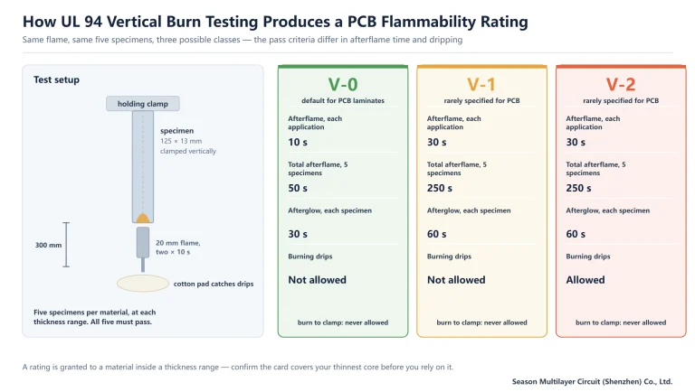
| Flammability | V-0 | UL 94 | Market access; confirm the thickness range on the yellow card |
Two habits save rework. First, always state the test method beside a Tg figure, because DSC and DMA results for the same material differ by several degrees and a purchase order that says only “Tg 180” leaves the supplier free to quote either. Second, check the UL listing against the thickness you actually need: a V-0 rating is granted for a range of constructions, as published on the UL Solutions product databases, and a thin core outside that range is not covered even though the grade name is identical.
Tg 180 and Td 355: What the Numbers Do and Do Not Promise
Tg is a transition, not a rating. At 180 °C the resin softens, the Z-axis expansion coefficient jumps from 41 to 208 ppm/°C and the modulus falls. Nothing is destroyed at that temperature, but the board has stopped behaving like the rigid structure the design assumed. A product that runs anywhere near Tg has a mechanical problem, not a material problem, and no laminate upgrade fixes a thermal design that lets a hotspot sit at 170 °C.
Td describes something different: the temperature at which the resin loses 5% of its mass, here 355 °C. It is the margin against chemical breakdown during assembly, and with lead-free reflow peaks of 245–260 °C it leaves roughly 95 °C of headroom before decomposition begins. That headroom covers multiple reflow passes, rework and press excursions, which is exactly why a grade with Td near 300 °C behaves nervously on a lead-free line even when its Tg looks adequate.
The trio that operational buyers should look at first is T260, T288 and T300: the time the laminate withstands a given temperature under load before delaminating. On the S1000-2M laminate they read above 60 minutes, 30 minutes and 15 minutes. A T288 of 30 minutes means the material tolerates a solder float at 288 °C for half an hour before separation, which is a far more honest predictor of press and reflow behaviour than any single transition point.
Z-Axis CTE and Through-Hole Reliability: The Real Selection Driver
A plated through-hole is a copper tube bonded to a laminate that expands about two and a half times faster than the copper inside it before Tg, and more than ten times faster above Tg. Copper moves at roughly 17 ppm/°C; the S1000-2M laminate moves at 41 ppm/°C below Tg and 208 ppm/°C above it. Over a 50–260 °C excursion the laminate grows 2.4%, and the barrel has to absorb that difference in tension, cycle after cycle, with no way to relieve it.
The arithmetic is worth running once. On a 2.4 mm thick board, 2.4% expansion is about 58 µm of growth across the hole depth. The copper cannot grow 58 µm longer without yielding, so the barrel is plated with enough ductile copper and enough thickness to stretch rather than tear. That is the physical reason IPC-6012 sets minimum plating in the barrel and why Class 3 asks for more copper than Class 2, and it is also why a high-aspect-ratio design concentrates the whole problem into a narrower tube.
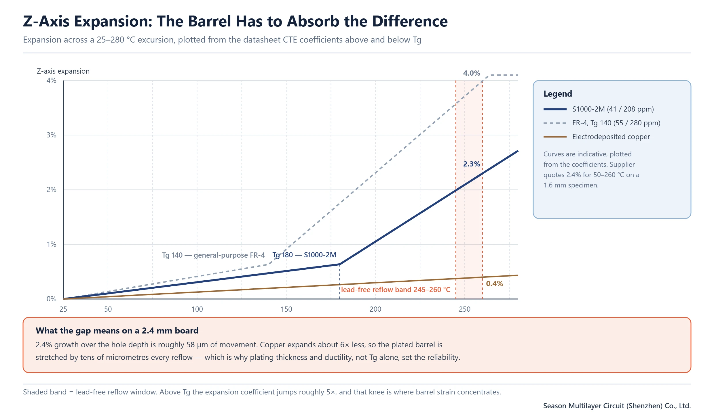
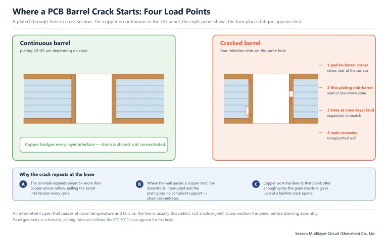
Expansion also explains the failure location. The highest strain sits where the barrel meets the surface pad and at the knee where a drilled wall transitions into the target land, which is where cross-sections almost always show the crack. Our own process limits follow from the same logic: through-holes at 12:1 in production and 20:1 on sample builds, with blind microvias held at 1:1, as listed on the aspect ratio and plating limits page.
Dk 4.6 and Df 0.018: Where This Material Still Works
Dk sets geometry and Df sets loss. On the S1000-2M laminate, Dk 4.6 means the trace width for 50 Ω at a given dielectric thickness is wider than it would be on a 3.8 or 3.3 material, which costs routing density on inner layers but is entirely predictable in field solving. Df 0.018 at 1 GHz is the standard-loss figure, and it is perfectly serviceable for the majority of digital boards: control, power, industrial, automotive body electronics and most consumer products never see a loss budget where this number is the limiting factor.
The cut-over point is a length-and-rate question, not a material question. Short runs of multi-gigabit lanes usually close on standard-loss epoxy; long backplane traces at 10 Gbps and above generally do not, and that is when the specification moves to a low-loss grade. As a working reference, a material such as TU-872 SLK at Dk 3.8 and Df 0.009 roughly halves the dielectric loss contribution and also buys thinner traces for the same impedance.
Mixed constructions are the usual answer for boards that carry both. Power and slow signal layers stay on S1000-2M, the high-speed layers move to a low-loss material, and the stackup is bonded with a press cycle compatible with both. That hybrid route is cheaper than making the whole board low-loss and far more robust than trying to squeeze a loss budget out of a standard epoxy by tightening impedance alone. Impedance tolerances of ±10%, ±8% or ±5% are available and should be stated per layer, not per board.
S1000-2M vs S1170G vs S1150G: Choosing on the Ladder
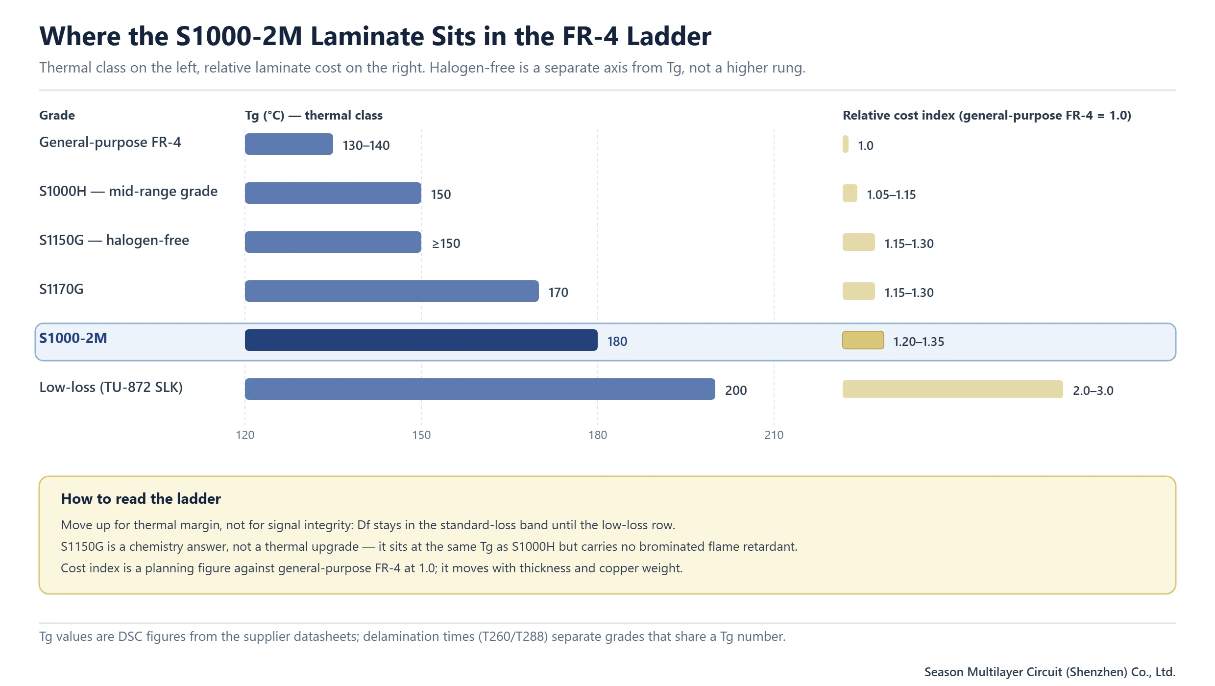
Grades in the same FR-4 family are separated by thermal class and flame-retardant chemistry, not by magic. Ordering them by Tg gives a ladder that makes selection straightforward once the requirement is written down as a number. The cost column below is a relative index against a general-purpose FR-4 taken as 1.0; it is a planning figure, not a quotation, and it moves with thickness and copper weight.
| Grade | Tg | Flame retardant | Relative laminate cost | Typical fit |
|---|---|---|---|---|
| General-purpose FR-4 | 130–140 °C | Brominated | 1.0 | Consumer boards, single reflow, moderate layer counts |
| S1000H | 150 °C | Brominated | 1.05–1.15 | Mid-range multilayer work where Tg 140 is marginal |
| S1150G | ≥150 °C | Halogen-free | 1.15–1.30 | Programmes with a halogen-free mandate, same thermal class |
| S1170G | 170 °C | Brominated | 1.15–1.30 | Thicker multilayers, tighter thermal cycling requirements |
| S1000-2M | 180 °C | Brominated | 1.20–1.35 | High layer counts, thick boards, repeated reflow, anti-CAF demand |
| Low-loss grade (TU-872 SLK class) | 200 °C | Brominated | 2.0–3.0 | 10G+ lanes over long traces, tight loss budgets |
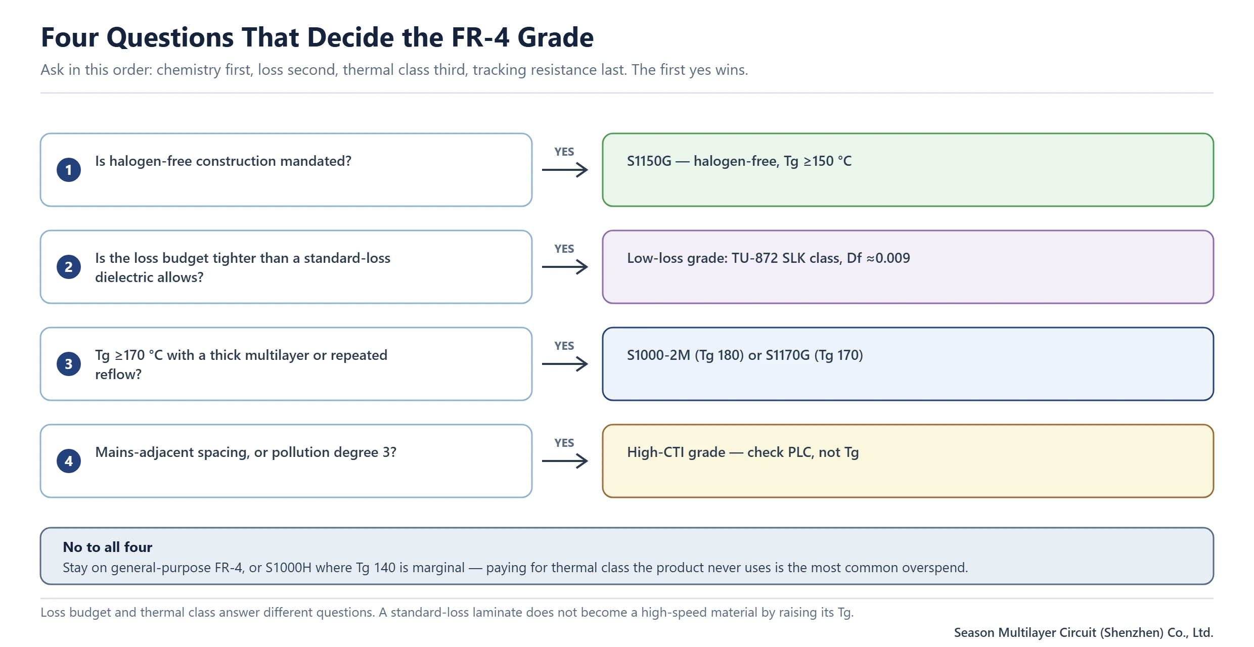
Two rules cut most of the argument. If the requirement is halogen-free, the thermal class does not decide the choice, chemistry does, and S1150G is the answer. If the requirement is a loss budget, no standard-loss grade qualifies regardless of Tg, and the ladder should be entered at the low-loss row. Everything between those two extremes is a genuine thermal decision, and there the tie-breaker is Z-axis expansion rather than Tg, because expansion is what loads the barrel.
CTI PLC 3 and Creepage: The Line Buyers Skip
For the S1000-2M laminate the datasheet lists CTI as PLC 3 under IEC 60112, which corresponds to a comparative tracking index in the 250–399 V band. For a low-voltage digital board this is irrelevant. For anything switching mains, or for a product with a high-pollution-degree environment, it is the number that sets minimum creepage distance between live conductors on the same layer, and it is frequently discovered late, after spacing has been fixed by mechanical constraints.
Do not assume a thermally strong grade automatically has strong tracking resistance. CTI depends on resin chemistry and filler loading, and it is common for a Tg 180 laminate to sit at PLC 3 while a specific high-CTI grade reaches PLC 0 or PLC 1. If the product needs both thermal margin and a high CTI, the requirement has to be checked as two separate columns, and the options compared on the CTI ratings and creepage guide before the stackup is frozen.
Processing the S1000-2M Laminate in a Production Shop
The press window for the S1000-2M laminate is a cure above 60 minutes at 185–195 °C, with the heat-up rate set by the inner-layer copper distribution and the structure of the multilayer rather than by a fixed recipe. Boards with heavy inner copper need a slower ramp so the resin flows and gels evenly; thin cores with light copper can be pushed harder. Prepreg is S1000-2MB, and the glass style plus resin content has to be chosen against the target dielectric thickness, not by habit.
| Glass style | Resin content | Cured thickness | Where it is used |
|---|---|---|---|
| 106 | 72–77% | 0.050–0.060 mm | Very thin dielectric for fine-pitch impedance control |
| 1080 / 1078 | 64–69% | 0.072–0.086 mm | Standard thin prepreg in HDI and high-density builds |
| 2313 / 3313 | 56% | 0.096 mm | Intermediate thickness with good flow |
| 2116 | 51–57% | 0.108–0.127 mm | Workhorse ply for multilayer bonding |
| 1506 | 45% | 0.150 mm | Thicker dielectric where ply count must stay low |
| 7628 | 44–52% | 0.187–0.227 mm | Thick cores and structural plies in heavy boards |
Drilling and desmear deserve attention because a Tg 180 resin is more brittle than a Tg 140 system. Tool wear accelerates, smear is harder to remove cleanly and the wall quality that plating depends on degrades faster, so hit counts and bit change intervals should be tighter than a general-purpose FR-4 recipe. Storage rules are equally practical: three months below 23 °C and 50% RH, six months below 5 °C with at least four hours of normalisation before use, because damp prepreg quietly costs bond strength.
When the S1000-2M Laminate Is the Wrong Call
Specifying a thermal grade to solve a signal-integrity problem is the most common misuse. If the failure mode is loss, crosstalk or an impedance that will not close, moving up the thermal ladder changes nothing except cost and lead time; the material has to move sideways into the low-loss family instead. Equally, if the mandate is halogen-free for market or customer reasons, a brominated grade cannot be argued into compliance by thermal margin.
There are three more cases worth flagging early. A 2-layer consumer board with a single reflow gains nothing from a Tg 180 core and pays for it on every panel. A design that needs PLC 0 or PLC 1 tracking resistance needs a CTI grade rather than a thermal grade. And a backplane pushed past a 12:1 aspect ratio has a geometry problem that no laminate solves, because the plating throw, not the resin, is what fails.
- Loss budget tighter than a standard-loss material can meet: move to a low-loss grade, not up the thermal ladder.
- Halogen-free required by the customer or the market: specify the halogen-free grade directly.
- High CTI needed for mains-adjacent or pollution-degree-3 spacing: check CTI as a separate requirement.
- Aspect ratio beyond 12:1 in production: redesign the hole or the thickness before changing material.
- Low-cost, low-layer-count, single-reflow product: a general-purpose grade is the correct engineering answer.
What to Put on the Fabrication and Purchase Documents
Most material disputes are documentation disputes, and most of them start with a purchase order that names a grade without naming its test conditions. A purchase order that names a grade but not a test method, a thickness range or a prepreg allows a legitimate supplier to deliver something that meets the wording and not the intent. The list below is the minimum that closes that gap, and it costs one paragraph in the fabrication drawing.
- Laminate grade and the matching prepreg designation, with the supplier named and the IPC-4101 slash sheet quoted as reference.
- Tg with the test method stated (DSC or DMA), plus Td and the T260/T288 values required for the assembly process.
- Finished thickness, copper weight per layer and the glass style plus resin content for each dielectric.
- UL grade and file reference, and the thickness range actually covered by the V-0 listing.
- IPC-6012 performance class, plating minimums in the barrel and the coupon used to prove them.
- Impedance targets with tolerance per layer, and the coupon design that will be measured.
- Any anti-CAF or moisture-resistance test the programme requires, with the acceptance criterion written out.
When those seven lines are present, a first-article report becomes a verification exercise rather than a negotiation. When they are missing, the buyer discovers the gap at the worst possible moment, usually when a cross-section shows a barrel that is thinner than expected in a lot that was already assembled.
Frequently Asked Questions
What is S1000-2M laminate?
It is a woven-glass epoxy laminate from Shengyi Technology with a Tg of 180 °C by DSC (185 °C by DMA), classified as UL / ANSI FR-4.0 and referenced to IPC-4101/126. It is supplied with S1000-2MB prepreg and is used mainly for high layer counts and thick boards that go through repeated lead-free reflow.
Is S1000-2M a halogen-free material?
No. It is a brominated FR-4.0 system. If a programme requires halogen-free construction, the grade to specify is S1150G, which has a Tg at or above 150 °C and no brominated flame retardant. Confusing the two is one of the most common material specification errors we see at CAM review.
What does a Tg of 180 °C mean in practice?
It means the resin transition sits at 180 °C, above which expansion rises from 41 to 208 ppm/°C. It is a process headroom figure, not a service temperature. A board that runs near 180 °C in operation has a thermal design problem, and no laminate upgrade removes the heat.
How does S1000-2M compare with S1170G?
Both are brominated FR-4 grades; S1000-2M is specified at Tg 180 with lower Z-axis expansion and longer delamination times, while S1170G sits at Tg 170. For moderately thick multilayers the two overlap in practice, and S1170G is often the more economical fit. For the thickest boards with repeated reflow, the S1000-2M laminate is the safer choice.
Can S1000-2M be used for high-speed signals?
For short multi-gigabit runs it can, but its Df of 0.018 at 1 GHz is a standard-loss figure. Long backplane traces at 10 Gbps and above usually need a low-loss grade such as TU-872 SLK at Df 0.009. Hybrid stackups, with power and slow layers on the S1000-2M laminate and high-speed layers on a low-loss material, are the usual compromise.
What prepreg goes with S1000-2M laminate?
S1000-2MB is the matching bonding prepreg, available in glass styles from 106 through 7628 with resin contents from about 44% to 78%. The cured ply thickness ranges from roughly 0.050 mm to 0.227 mm, so dielectric thickness targets are met by ply selection and resin content rather than by pressing a single heavy ply.
What is the press cycle for this grade?
Curing above 60 minutes at 185–195 °C, with the heat-up rate set by the inner-layer copper distribution and the multilayer structure. Heavy copper needs a slower ramp for even resin flow. Prepreg should be stored below 23 °C and 50% RH for up to three months and normalised for at least four hours before use, and those rules apply to the S1000-2M laminate as supplied.
Does S1000-2M have high tracking resistance?
Its CTI is PLC 3 under IEC 60112, which corresponds to roughly 250–399 V. That is normal for a standard epoxy system and is not a high-CTI grade. Products switching mains voltage or operating at pollution degree 3 need CTI checked as a separate requirement before the stackup is released.
Have the Stackup and Material Call Checked Before Release
If the stackup, the assembly profile and the target market are already defined, send them for review and the Season PCB engineering team will confirm whether the S1000-2M laminate is the right level, whether a halogen-free or low-loss route is needed instead, and which prepreg combination meets the dielectric thickness. Reviews happen before quotation, so a material mismatch is caught while it is still a drawing change rather than a re-spin. See how we handle material and construction review, or submit Gerber data for a first pass.
Season PCB direct: Tel (+86) 18681528532 | WhatsApp +86 18681528532
E-mail: roc@season-pcb.com