Book Appointment Now

Via tenting seals the via opening under solder mask while plugging fills the barrel with ink or resin. Compare process flow, cost and when each finish is required.
Via Tenting vs Via Plugging: How to Choose the Right Via Finish
Every multilayer board carries dozens to thousands of vias, and each one needs a decision: leave the opening tented under solder mask, or plug the barrel solid. The choice looks minor on a fab note, but it changes soldering behaviour during assembly, long-term reliability, and the cost of the build. Picking the wrong one for a BGA field or a via-in-pad design is a rework order waiting to happen.
This guide compares via tenting and via plugging as a manufacturer sees them: how each process actually runs, where each is the right call, what acceptable fill quality looks like, and how to specify the treatment on your fabrication drawing so nothing is left to interpretation.
Table of Contents
- What Via Tenting and Via Plugging Actually Mean
- How Each Process Runs on the Production Line
- Via Tenting vs Via Plugging: Side-by-Side Comparison
- Where Via Tenting Is the Right Choice
- Where Plugged Vias Are Required
- Plug Fill Quality: What Acceptance Looks Like
- Reliability and Cost Trade-offs, Honestly Stated
- How to Specify the Via Finish on Your Fabrication Drawing
- Common Defects and How Capable Factories Prevent Them
- FAQ
- Get Your Via Treatment Reviewed With Your Stackup
What Via Tenting and Via Plugging Actually Mean
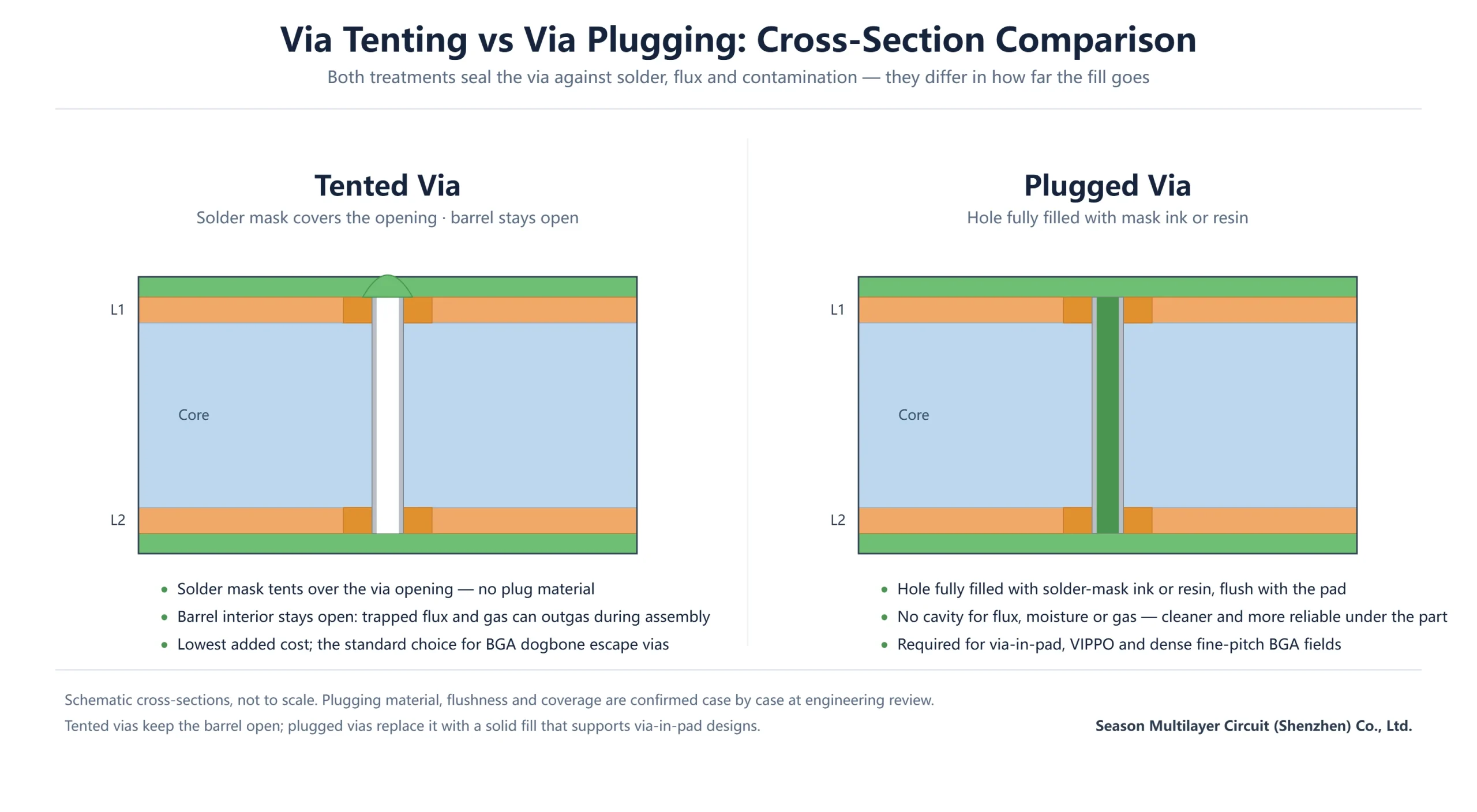
Via tenting means covering the via opening — and usually the surrounding annular ring — with solder mask, so the plated barrel is sealed underneath a dome of mask. The hole itself is never filled: the barrel interior stays open, and the mask is the only barrier between the copper bore and the outside world. It is the default treatment on most designs because it adds essentially no dedicated process step; on fabrication drawings the treatment is usually written simply as solder mask over via, since the mask covers the hole without filling it.
Via plugging goes further: the barrel is filled end to end with a plug material — typically a solder-mask ink or a resin — cured and then planarized so the plug sits flush with the surface pad. There is no cavity left inside the hole at all. Unlike via tenting, plugging is a separate production step with its own equipment and inspection, which is exactly why it is specified selectively rather than applied to every via on the board.
How Each Process Runs on the Production Line
Via tenting rides on the standard solder-mask operation. After the mask is printed and pre-cured, the openings over tented vias stay covered while every other pad is developed clear. Because a single print may not fully bridge a large hole, mask coverage over tented vias is often built up with a second print pass; hole size matters too, and factories flag oversized vias that a mask bridge cannot seal reliably.
Plugging is its own station. Panels run through a dedicated plugging machine that pushes ink or resin into each hole under pressure or vacuum, the plug is cured, and the surface is sanded or planarized flush before final mask print. That is why plugged vias cost more than tented ones: the extra steps, the consumable, and the inspection all add up. The premium is usually a modest multiplier on the affected layers rather than on the whole build, depending on how many vias are plugged and where.
One more distinction matters for sourcing: plugging is not the same as via filling with copper. Electroplated via filling is a different, heavier process reserved for stacked-via HDI structures; if that is your case, the trade-offs are covered in the guide to resin plugging versus solder mask ink plugging.
Via Tenting vs Via Plugging: Side-by-Side Comparison
The two treatments answer different problems. Tenting is about keeping solder, flux and contamination out of a hole that will never carry a component; plugging is about making the via a solid, planar structure that can sit under a part or survive demanding environments. The table summarises the practical differences.
| Aspect | Tented via | Plugged via |
|---|---|---|
| Hole interior | Open barrel sealed under a mask dome | Fully filled with ink or resin, flush with the pad |
| Main purpose | Block solder wicking and flux entry during assembly | Enable via-in-pad, protect against entrapment, support fine-pitch fields |
| Process impact | No dedicated step — handled in normal mask printing | Separate plug, cure and planarize steps with dedicated tooling |
| Added cost | Minimal | Moderate multiplier on affected holes or layers |
| Typical failure mode | Mask bridge cracks on oversized holes; trapped flux outgassing | Voids, incomplete fill, or plug shrinkage if process control slips |
| Best suited for | BGA dogbone escapes, general routing vias away from pads | Vias under components, VIPPO, dense BGA and HDI structures |
Read the table as a decision aid, not a ranking. A board full of tented vias is not under-engineered, and a board full of plugged vias is not automatically more reliable — each treatment simply fits different via locations, which is what the next two sections sort out. Framed that way, tenting vs plugging is a mapping from via location to treatment, not a preference.
Where Via Tenting Is the Right Choice
Tenting earns its keep wherever the hole only needs to stay empty and clean. Escape vias fanning out from a BGA perimeter are the classic case: during reflow, an open via next to a pad will wick solder away from the joint and star it, and a tent stops that. Run this check across the drill map and the via tenting versus plugging split usually settles in minutes. The same logic applies to routing vias in open field areas, test-access vias that will not be probed after assembly, and any hole far enough from solderable pads that contamination is a non-issue.
The limitation is structural. A tent is a thin mask bridge over an open cavity — it is not designed to be printed over, placed on, or pressed by a component. Under a BGA body the trapped air and residual moisture in open barrels can outgas during reflow, popping the mask or voiding nearby joints. And if a design later moves a via underneath a pad, tenting stops being an option entirely; that is a plugging job, as explained in the via-in-pad process guide.
Where Plugged Vias Are Required
Plugging is mandatory, not optional, in three situations. First, via-in-pad: when a via sits inside a component pad, the barrel must be filled and planarized or the pad will not hold a solder joint. Second, dense fine-pitch BGA fields, where open vias between tight pads rob solder and create shorting paths during assembly. Third, HDI and stacked-via structures, where every microvia in the stack must be filled before the next layer pair is built up. The stackup guides for the 10-layer 2-stage HDI prototype PCB and the 12-layer 1-stage HDI core board PCB both show plugged microvias in their build tables.
Environment can also drive the decision. Boards destined for high-humidity or thermally cycling industrial service benefit from plugged vias because there is no cavity to breathe — no path for moisture ingress, no outgassing pressure under the mask. For general industrial designs such as the boards on the 10-layer HDI industrial control PCB page, plugging is applied to the vias that need it and tenting to the rest, which keeps the build economical.
Plug Fill Quality: What Acceptance Looks Like
Because plugging is a real process, it has real acceptance criteria. The parameter factories grade is the plugged via fill ratio — how completely the plug occupies the barrel, checked on microsection or high-magnification inspection. The commonly used bands are summarised below.
| Observed fill | Workmanship grade | Notes |
|---|---|---|
| 90–100% of barrel | Ideal | Minor dimple at the mask side is acceptable on most classes |
| 80–90% of barrel | Acceptable | Common on dense fields; acceptable unless the via sits under a pad |
| Over 100% (plug bulges above surface) | Not recommended | Bulge planarizes poorly and can tilt small components |
| Under 50% of barrel | Not recommended | Reserved at most for holes to be sealed later under mask; otherwise reject |
The defects that matter alongside fill ratio are voids inside the plug, cracks that transmit light through the section, and solder-ball contamination from sloppy ink handling. Formal via-protection categories — tented, plugged, filled and capped structures — are standardised in IPC-4761, and referencing the type designators on your fab drawing removes most ambiguity before quoting. Via tenting, plugging and copper filling each sit among these designations, and the table below maps the full set.
| IPC-4761 type | Structure it designates | Typical drawing use |
|---|---|---|
| Type I | Covered — mask material lies over the opening, barrel open | Covered vias where the mask alone must bridge the hole |
| Type II | Tented — mask spans the opening and the annular ring | Standard via tenting on escape and routing vias |
| Type III | Filled and covered | Vias that must be sealed before a second mask print |
| Type IV | Filled and tented | Sealed vias kept under mask on the drawing |
| Type V | Plugged — barrel filled without a plated cap | Ink-plugged holes where no pad sits on the plug |
| Type VI | Plugged and covered | Plugged vias that must also sit under mask |
| Type VII | Plugged and encapsulated — filled, planarized and capped | Via-in-pad and dense BGA-field plugs called out flush |
Reliability and Cost Trade-offs, Honestly Stated
The cost difference is real but narrower than buyers often assume. Tenting is nearly free; plugging adds a process step whose impact depends on how many vias are plugged, the smallest hole size, and whether planarization is needed for via-in-pad. On a mixed board where only the BGA field is plugged, the premium is modest; on a board where every via is plugged for no stated reason, you pay for work the design does not use.
On reliability the logic is symmetrical. Via tenting holds up for the life of the product when the vias sit in appropriate locations — the failure stories almost always trace back to a tent used where a pad or a harsh environment demanded a plug. Conversely, plugging introduces its own risk only when process control slips: a voided plug under a BGA pad is worse than no plug at all. The engineering answer is to specify the treatment per via group rather than board-wide, and to treat plugging as a capability you audit, not a checkbox.
How to Specify the Via Finish on Your Fabrication Drawing
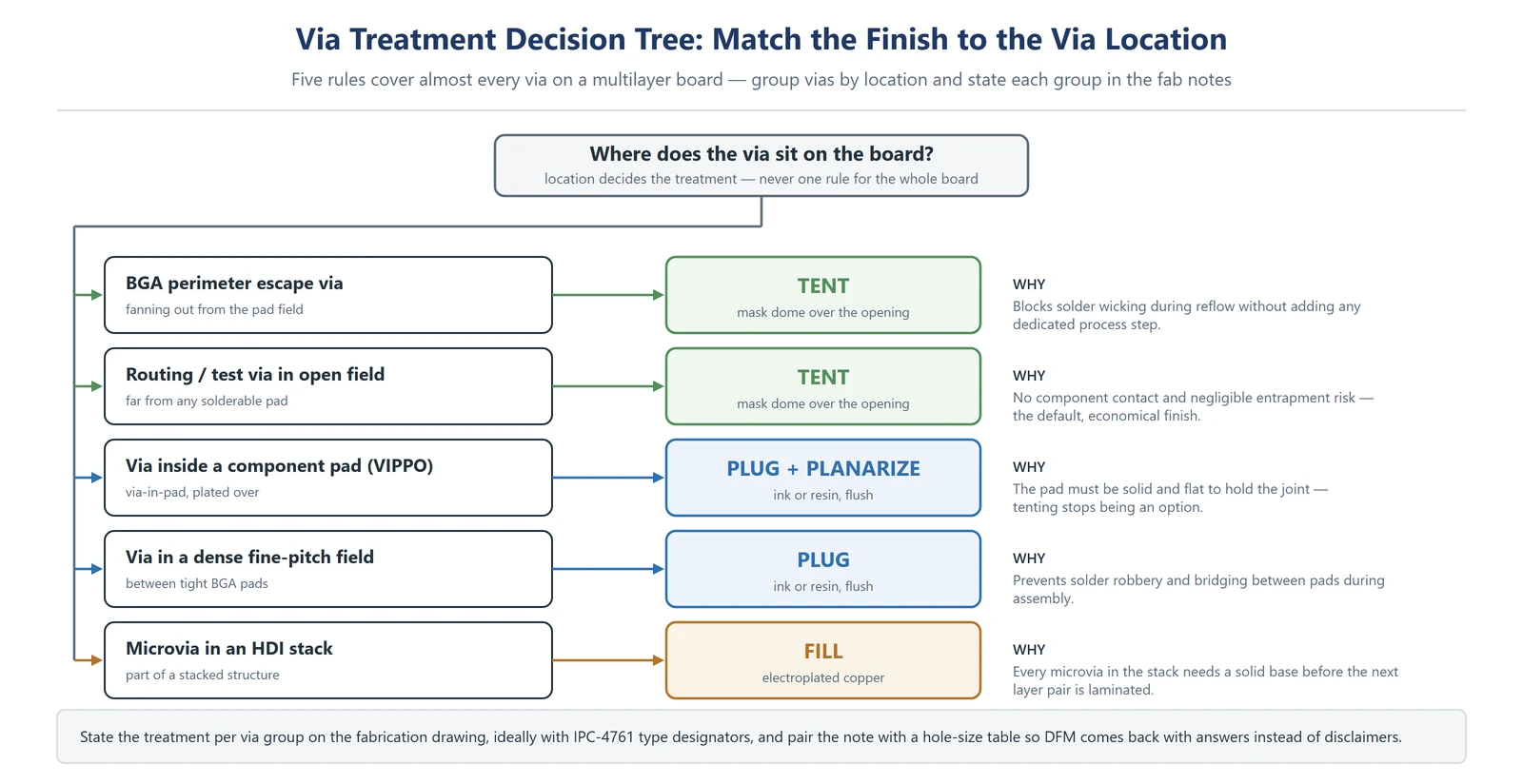
Ambiguous via notes are a top cause of quote mismatch, because factories have to guess and each guesses differently. State the treatment per via group in the fab notes, using the simple map below as a starting point, then let the DFM review confirm feasibility against your hole sizes and stackup. A complete via finish specification names the treatment, the fill material, and the acceptance check for every via group.
| Via location | Recommended treatment | Why |
|---|---|---|
| BGA perimeter escape via | Tented | Blocks solder wicking without adding cost |
| Via inside a component pad (VIPPO) | Plugged and planarized | Pad must be solid and flat to hold the joint |
| Routing via in open field | Tented | No component contact; entrapment risk negligible |
| Via in dense fine-pitch field between pads | Plugged | Prevents solder robbery and bridging |
| Microvia in an HDI stack | Filled before next lamination | Stacked structures require a solid base |
A good drawing note reads like: “All vias ≤0.3 mm in the BGA field to be filled with solder-mask ink, flush per IPC-4761 Type VII; all other vias tented.” Pair the note with a hole-size table and your supplier’s DFM response will come back with concrete questions instead of a disclaimer.
The decision tree condenses the five rules: via tenting where a via only needs to stay clean, plugging where a pad or a dense field needs a solid barrel, and copper fill where another stage will stack on top.
Common Defects and How Capable Factories Prevent Them
On the plugging side, the recurring defects are voids from trapped air, incomplete fill on small or high-aspect holes, plug shrinkage after cure, and overfill that bulges past the surface. Each maps to a process control. Vacuum-assisted plugging eliminates air; ink viscosity and screen parameters are matched to hole size; cure profiles are verified against material data sheets; and planarization is checked per panel rather than per lot.
On the tenting side, the failure mode is simpler: the mask bridge over a large or poorly sized hole cracks, either immediately or during thermal excursions. Prevention lives in design rules — keep tented hole sizes within what a mask bridge can span, avoid tenting vias that will sit under components, and flag any via that must stay open for test so the factory does not tent it by default. Cross-checking the via map against the stacked versus staggered via structures guide catches most conflicts before they reach the line.
Frequently Asked Questions
What is the difference between via tenting and via plugging?
Tenting covers the via opening with solder mask, leaving the barrel open underneath. Plugging fills the entire barrel with solder-mask ink or resin and planarizes it flush with the surface. Tenting is a byproduct of normal mask printing; plugging is a dedicated process step with its own cost and inspection criteria.
Is via tenting enough for vias under a BGA?
For vias on the BGA perimeter that only need to stop solder wicking, tenting is the standard and economical choice. For vias directly under the component body or in the pad field, tenting is not enough — trapped air and flux in open barrels can outgas and void joints, and via-in-pad designs require a plugged and planarized hole.
What fill ratio should a plugged via have?
Common workmanship bands grade 90–100% fill as ideal and 80–90% as acceptable for most locations. Overfilled plugs that bulge above the surface and plugs under 50% fill are both flagged. For vias inside component pads, most buyers specify the higher band plus planarization, verified on microsection.
Does plugging vias add cost to a PCB build?
Yes — plugging adds dedicated plug, cure and planarize steps, so it carries a moderate premium over tenting. The premium scales with the number and size of plugged vias and whether flush planarization is needed. Plugging only the vias that require it keeps the added cost proportionate.
Can a tented via fail during assembly?
It can. A mask bridge over an oversized hole may crack during reflow, and open barrels under a component can trap flux and moisture that outgas during thermal cycling. Both failure modes are avoided by keeping tented holes within bridging limits and by plugging any via that sits under a part or in a harsh environment.
What is a plugged via on a BGA pad (VIPPO)?
VIPPO — via-in-pad plated over — means the via inside the pad is plugged, then plated over so the pad surface is continuous and flat. It shortens the escape path on dense BGA designs and improves heat spreading, but it requires a solid plug and planarization to solder reliably, so it always implies plugging rather than tenting.
How do I specify tenting or plugging on my fab drawing?
Group vias by location and state the treatment for each group in the notes, ideally with IPC-4761 type designators — for example, vias in the BGA field filled and planarized to Type VII, all other vias tented. Add a hole-size table so the factory can confirm bridging limits and plugging feasibility during DFM review.
Get Your Via Treatment Reviewed With Your Stackup
Send your Gerber set and via map for engineering review before release: the review confirms which vias to tent, which to plug, and what fill and planarization your BGA and HDI structures actually need. Fabrication supports 2–30 layer builds with resin plugging and electroplated via filling, 0.1 mm laser microvias as standard, and IPC-4761-conformant via protection across the 998 PCB Group’s three plants, with the DFM response scoped to the same package.