Book Appointment Now

How high CTI PCB laminates earn their premium: the 600 V threshold, creepage rules on dense layouts, what changes in production and how to verify a claim.
High CTI PCB Explained: Ratings, Creepage Rules and Material Choice
Insulation failures rarely announce themselves. A power board that behaves on the bench can start tracking across the laminate surface years into field service, wherever humidity, dust and working voltage coincide. That failure mode is what the comparative tracking index was written to measure, and it is the reason a high CTI PCB exists as a distinct material class rather than a marketing label. This article explains what the rating means, how it converts into layout rules, and where it genuinely earns its premium.
The guide is written for hardware engineers and buyers. It separates the measured number from the derived labels, shows the creepage arithmetic that makes the rating commercially interesting, lists what actually changes in production, and closes with the documents to demand before you commit a design.
Table of Contents
- What CTI Means and How the Test Works
- CTI, PTI, UL PLC and IEC Material Groups: Four Labels, One Test
- How a High CTI PCB Buys Back Creepage on Dense Layouts
- What Makes a High CTI PCB Laminate Tracking Resistant
- What Changes on the Shop Floor for a High CTI PCB Build
- Where the Cost of a High CTI PCB Actually Goes
- Applications Where a High CTI PCB Pays Off
- How to Verify a High CTI PCB Claim Before Production
- Specifying a High CTI PCB on the Stackup Drawing
- Frequently Asked Questions About High CTI PCB
- Have Your Stackup Reviewed for Tracking and Creepage
What CTI Means and How the Test Works
CTI stands for comparative tracking index. It is defined in IEC 60112, the international test method for solid insulating materials: standardized electrodes rest on a flat specimen, a contaminant solution is dripped between them at a fixed rate, and voltage is applied in steps. The reported CTI is the maximum voltage at which the specimen survives 50 drops without forming a conductive track. You can read the scope of the current edition on the IEC 60112 publication page.
Two details of the method matter in practice. First, the CTI number and the pass/fail PTI number come from the same apparatus, but they answer different questions — one characterizes the material, the other checks it against a threshold. Second, the method was written for AC test voltages up to 600 V, because above that level the test loses severity rather than gaining discrimination. When a data sheet claims a value far beyond that range, the claim has travelled outside the measurement that defines it.
For context, ordinary FR-4 typically publishes a CTI between 200 V and 400 V. A high CTI PCB starts at 600 V, with the best modified epoxies sitting at the top of the scale. The jump is not incremental; it reflects a different resin and filler chemistry, which is why the rating cannot be ordered as an afterthought.
CTI, PTI, UL PLC and IEC Material Groups: Four Labels, One Test
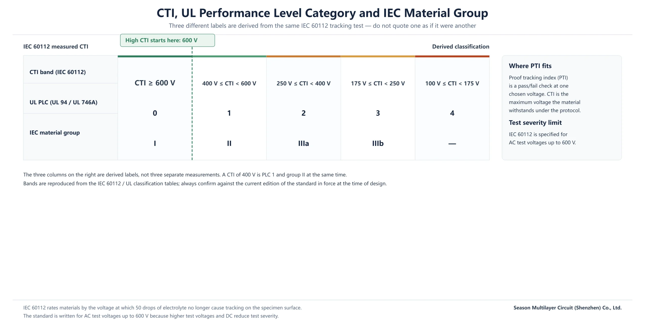
One measurement, several labels. The measured CTI voltage band maps onto a UL performance level category (PLC 0 through 4) and onto the IEC material group (I to IIIb) that creepage tables reference. A laminate measuring exactly 600 V is simultaneously PLC 0 and material group I. Mixing the labels up in a drawing note is a common and avoidable defect.
| CTI band (IEC 60112) | UL PLC | IEC material group | Typical interpretation |
|---|---|---|---|
| CTI 600 V and above | 0 | I | High CTI class; shortest creepage allowances |
| 400 V up to 600 V | 1 | II | Good general-purpose insulation |
| 250 V up to 400 V | 2 | IIIa | Standard FR-4 territory |
| 175 V up to 250 V | 3 | IIIb | Dry, benign environments only |
| 100 V up to 175 V | 4 | — | Severely restricted; unsuitable for line-voltage work |
Treat the band edges with respect and quote the standard with its edition. Classification tables get revised, and a note that says material group I without naming the test edition invites an argument with a safety engineer later. Where a certification claim matters, the UL Solutions yellow card is the public document that carries the PLC, and it is the fastest cross-check a buyer can run.
How a High CTI PCB Buys Back Creepage on Dense Layouts
Product safety standards rarely ask for a CTI number directly. They ask for a creepage distance — the shortest surface path between two conductive parts — and the required distance depends on the working voltage, the pollution degree of the environment and the material group. CTI enters through the back door: the higher the CTI, the better the material group, and the shorter the required creepage.
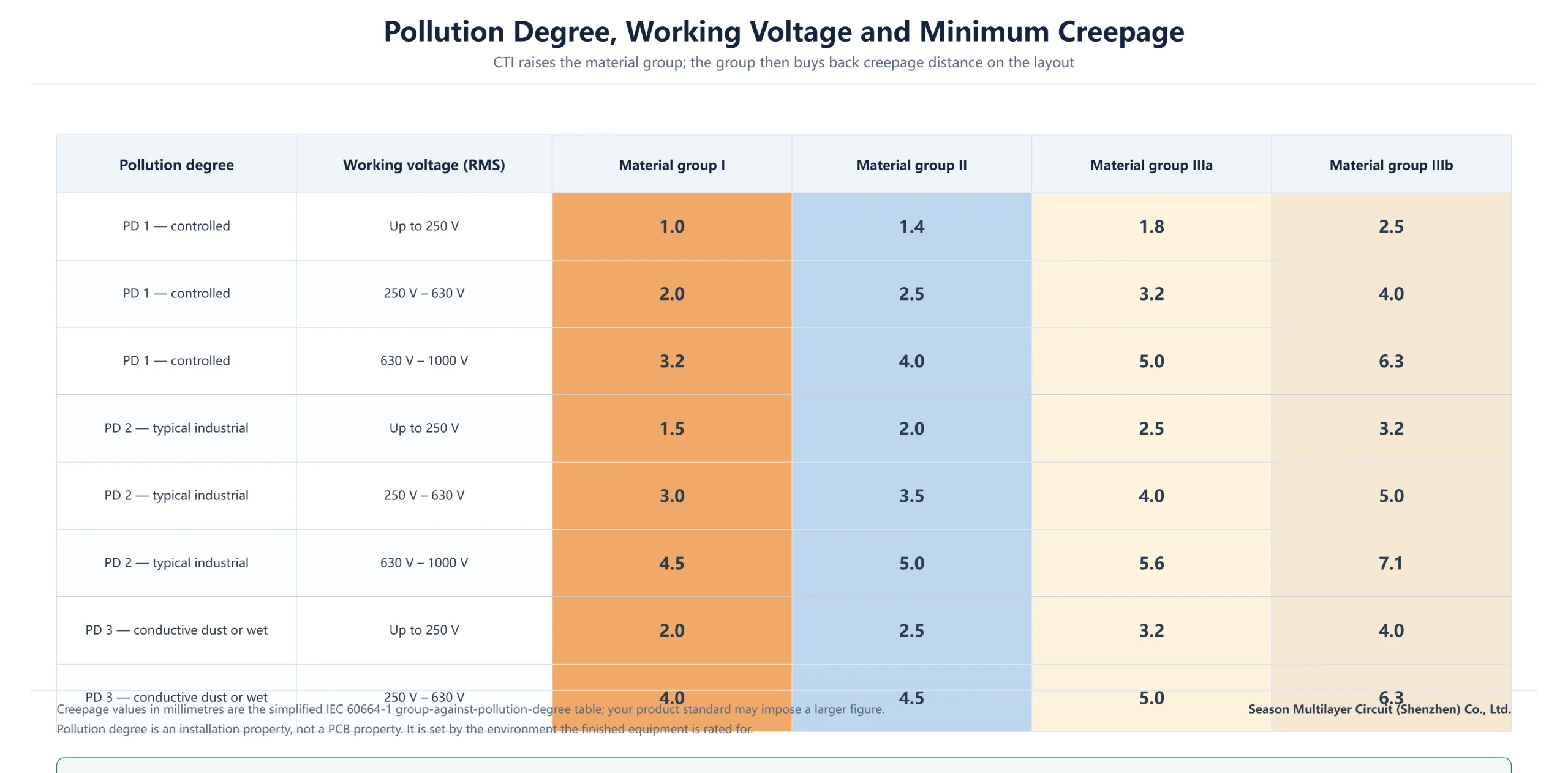
The savings are concrete. Under the simplified IEC 60664-1 tables, 250 V of working voltage in pollution degree 2 needs 1.5 mm of creepage for a group I material but 2.5 mm for group IIIa. On a dense power supply or inverter board, one millimetre of creepage across every isolation boundary is layout space you cannot buy back any other way.
Read the table backwards and the commercial case appears. If the enclosure cannot grow and the spacing rules cannot shrink, the material is the remaining lever. That is the honest reason engineers specify a high CTI PCB: not for the number itself, but for the distance it returns to a crowded layout. Our PCB materials and laminates guide covers the rest of the material trade-offs that sit alongside this one.
What Makes a High CTI PCB Laminate Tracking Resistant
Tracking begins when contamination and moisture form a weakly conductive film on the surface, current concentrates through it, and the organic resin carbonizes. Carbon conducts, so the damage feeds itself. Laminate chemistry fights the mechanism on three fronts.
- Modified epoxy resin systems with high purity and low moisture uptake, so the surface stays less hospitable to conductive films.
- Inorganic filler packages — alumina trihydrate among them — that release water as they heat, quenching the carbonization reaction before it sustains itself.
- Dense, low-impurity glass fabric that leaves fewer sites for moisture to lodge and for local electric fields to concentrate.
None of these are tricks a fabricator can add at the press. They are formulated into the laminate, which is why the CTI value belongs to the material designation, not to the board shop. When a high CTI PCB is specified by grade, the property travels with the laminate lot — and so does the burden of proof.
What Changes on the Shop Floor for a High CTI PCB Build
The fabricator’s contribution is keeping the margin the laminate brings. Moisture, residue and pressing defects each erode the surface condition the rating assumes, so a high CTI build tightens controls that a standard build treats loosely.
| Build step | Standard FR-4 practice | High CTI practice | What the buyer checks |
|---|---|---|---|
| Laminate incoming | Grade rarely stated | Tracking-tested grade with published CTI and PLC | Data sheet plus UL yellow card |
| Clean and dry | Standard surface clean | Multi-step clean and controlled low-temperature dry | Moisture control in the routing |
| Press cycle | One ramp and hold | Segmented ramp-and-hold with steady pressure | Lamination void record |
| Surface finish | Chosen by cost | Chosen against the field environment | Finish and thickness on the drawing |
| Final test | Continuity and isolation | Coupons at tracking-relevant spacings | Test report tied to the panel lot |
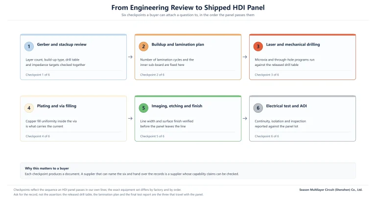
The gate that matters most is the stackup drawing. If the drawing names the laminate, the finish and the pressing note, every other row can be audited against it. If it does not, all of the claims above stay verbal. The same discipline is visible on our PCB manufacturing capability page, and it is the page we point buyers to before they send a tracking-sensitive design.
Where the Cost of a High CTI PCB Actually Goes
A high CTI PCB carries a premium over the equivalent standard FR-4 build, and it is worth knowing which levers drive it before negotiating. Roughly, expect the tracking-resistant resin system to add tens of percent to the laminate line item, with the remainder coming from handling and documentation discipline rather than from exotic processing.
| Cost driver | Direction | Relative magnitude | Notes |
|---|---|---|---|
| Tracking-resistant resin system | Up | Moderate | Laminate line item; varies by grade and thickness |
| Special laminate sourcing | Up | Low to moderate | Common grades are stocked; others need allocation |
| Tighter clean and dry controls | Up | Low | Process discipline, not new equipment |
| Creepage savings recovered | Down | Design-dependent | Smaller boards or fewer respins can offset the premium |
| Coupons and documentation | Up | Low | Quoted explicitly rather than buried in the unit price |
The offset most buyers miss sits at the system level. If the rating lets one isolation boundary shrink, the board may drop a size class, and the panel-utilization gain can exceed the laminate premium. Whether that works is a design question rather than a purchasing one, which is exactly why the decision belongs in the engineering review. Our PCB laminate selection guide walks the same logic for the other material dimensions.
Applications Where a High CTI PCB Pays Off
The rating earns its keep wherever three factors overlap: line voltage, contamination and continuous operation. Industrial power electronics is the textbook case — variable-frequency drives, servo amplifiers, PLC backplanes and switch-mode power supplies run for years in dusty, humid cabinets where standard surfaces slowly carbonize.
New-energy hardware raises the stakes. Photovoltaic inverters, EV charging infrastructure and battery management systems combine high working voltages with outdoor humidity cycling and condensation events. There, the creepage the rating buys back is often the difference between a compliant compact layout and an enclosure redesign. A representative example from our own production is the 10-layer HDI industrial control PCB, where dense interconnect and harsh-environment duty have to coexist on one board.
The same logic extends quietly into demanding consumer and commercial equipment: refrigeration controllers, dishwashers, coffee machines and HVAC boards all see moisture and line voltage together. In vehicle-adjacent and telecom power hardware, the rating also supports the internal approval processes customers run, even where the published standards do not name it explicitly.
How to Verify a High CTI PCB Claim Before Production
Verification is a documents exercise, and it starts before the purchase order. Ask for the four artefacts in the order they are produced, and check that they agree with each other.
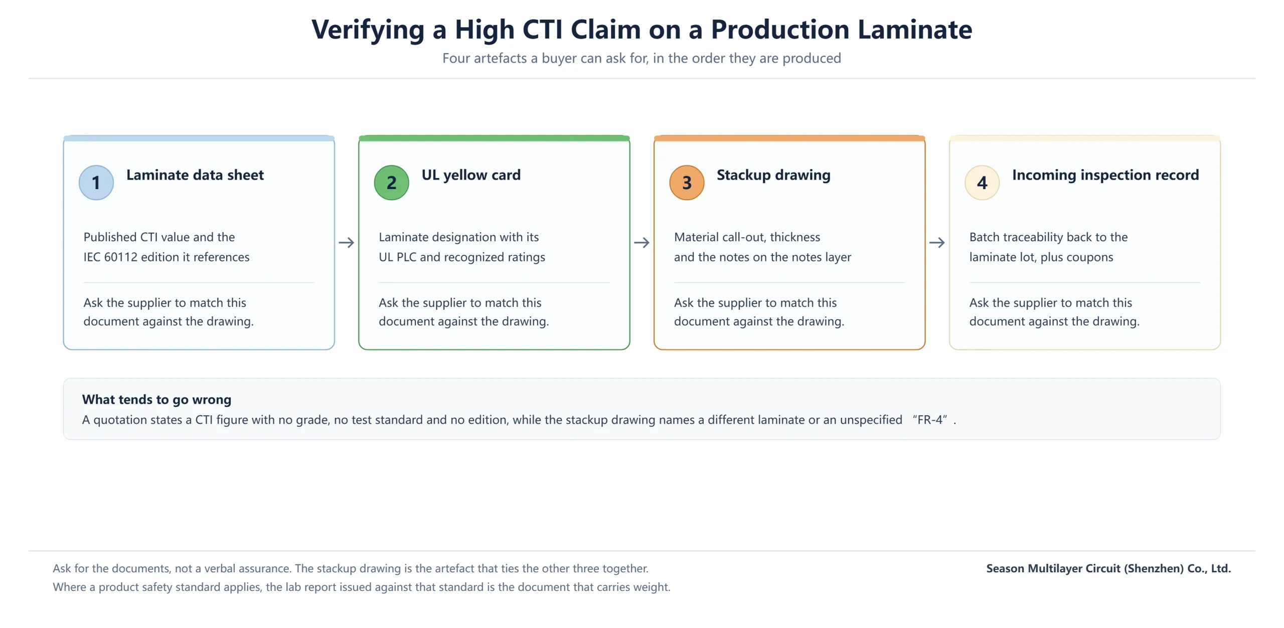
- The laminate data sheet, naming the grade, the measured CTI and the edition of IEC 60112 it references.
- The UL yellow card for that grade, showing the PLC and the recognized ratings.
- The stackup drawing, calling out the laminate by grade — not just FR-4.
- The incoming inspection or batch record, tying the panel lot back to the laminate lot.
A quotation that states a CTI figure with no grade, no standard and no edition is an assurance, not a specification. Where a product safety approval is involved, the lab report issued against that approval carries the weight with the certification body. IPC-A-600 acceptance criteria can be referenced through the IPC standards library for the visual and dimensional side, but tracking resistance itself is a material property, proven on paper. If the approval in question is a North American one, our cUL certification guide explains how the marks line up.
Specifying a High CTI PCB on the Stackup Drawing
The drawing is where intent becomes auditable. A specification that survives procurement and audits has three properties: it names the material, it names the property, and it names the test.
- Call out the laminate grade and thickness in the stackup, spelled exactly as the data sheet spells it.
- State the required property as a CTI value with the standard and edition — for example, CTI 600 per IEC 60112.
- Reference the surface finish and its expected thickness wherever creepage depends on it.
- Keep the note on the fabrication drawing, not buried in an email thread.
What to avoid is just as simple. Do not write high CTI FR-4 without a grade — that phrase is unenforceable. Do not ask for a CTI the laminate family cannot reach, and do not assume the property survives a substitution: if the shop proposes an alternate material, the CTI note is exactly what the alternate must satisfy.
Frequently Asked Questions About High CTI PCB
What CTI value counts as a high CTI PCB?
Industry convention treats 600 V as the threshold: it is the material group I boundary in the IEC classification tables and the point where creepage allowances shorten meaningfully. Conventional FR-4 typically publishes 200–400 V. The rating always belongs to the specific laminate grade, not to the board that uses it.
What is the difference between CTI and PTI?
Both come from IEC 60112 and use the same apparatus. The proof tracking index (PTI) is a pass/fail check at one chosen voltage — the figure that usually appears in a safety approval. The comparative tracking index (CTI) is the maximum voltage the material withstands under the full step protocol, which is why data sheets list it as a single measured value.
Is a higher CTI always the better choice?
No. The rating is one material property among several — glass transition temperature, decomposition temperature, loss tangent and cost all trade against it. For a dry, sealed product at low working voltage, a standard grade is the rational choice. High CTI earns its premium when line voltage, contamination and continuous operation coincide, or when the creepage it saves solves a real layout constraint.
How does CTI affect creepage and clearance on a dense layout?
Creepage — the shortest surface path between conductors — is set by working voltage, pollution degree and material group, and the material group comes from CTI. Moving from group IIIa to group I shortens the required 250 V pollution-degree-2 allowance from about 2.5 mm to about 1.5 mm. Clearance is a through-air dimension and is not affected by the material group.
Which laminate types deliver CTI 600 V and above?
Tracking-resistant modified epoxies with inorganic filler systems are the mainstream route, available from the major laminate producers in the same thickness ranges as standard FR-4. For a specific design, name the grade at engineering review: the published CTI and PLC travel with the grade, and availability varies by thickness and copper weight.
Does a high CTI PCB cost more than a standard FR-4 build?
Yes, moderately. The tracking-resistant resin system adds a premium to the laminate line, and tighter cleaning, drying and documentation add a smaller amount. The frequently missed offset is at the system level: shorter creepage allowances can shrink the board or eliminate an enclosure change, and that gain can exceed the material premium on dense power boards.
How do I verify that my panel really uses a high CTI laminate?
Ask for the laminate data sheet, the UL yellow card and the stackup drawing, and check that all three name the same grade. The incoming inspection record ties the panel lot back to the laminate lot. A verbal assurance, or a drawing that says only FR-4, is not verification — the property is a material designation, so it is proven on paper.
Have Your Stackup Reviewed for Tracking and Creepage
Send the Gerber data with the isolation boundaries marked, the working voltages across them, and the environment the product is rated for. The engineering team returns a stackup proposal with a named laminate grade, its published CTI and PLC, and the creepage assumptions the layout can rely on — before fabrication is quoted.
The review is part of our PCB manufacturing service, and it applies the same discipline from a single prototype panel through production volumes.