Book Appointment Now

What the S1000H laminate data sheet says: thermal margin from T288 and Td, a standard-loss electrical position, and the grade to use when bromine is banned.
S1000H Laminate: Mid-Tg FR-4 Properties and Assembly Window
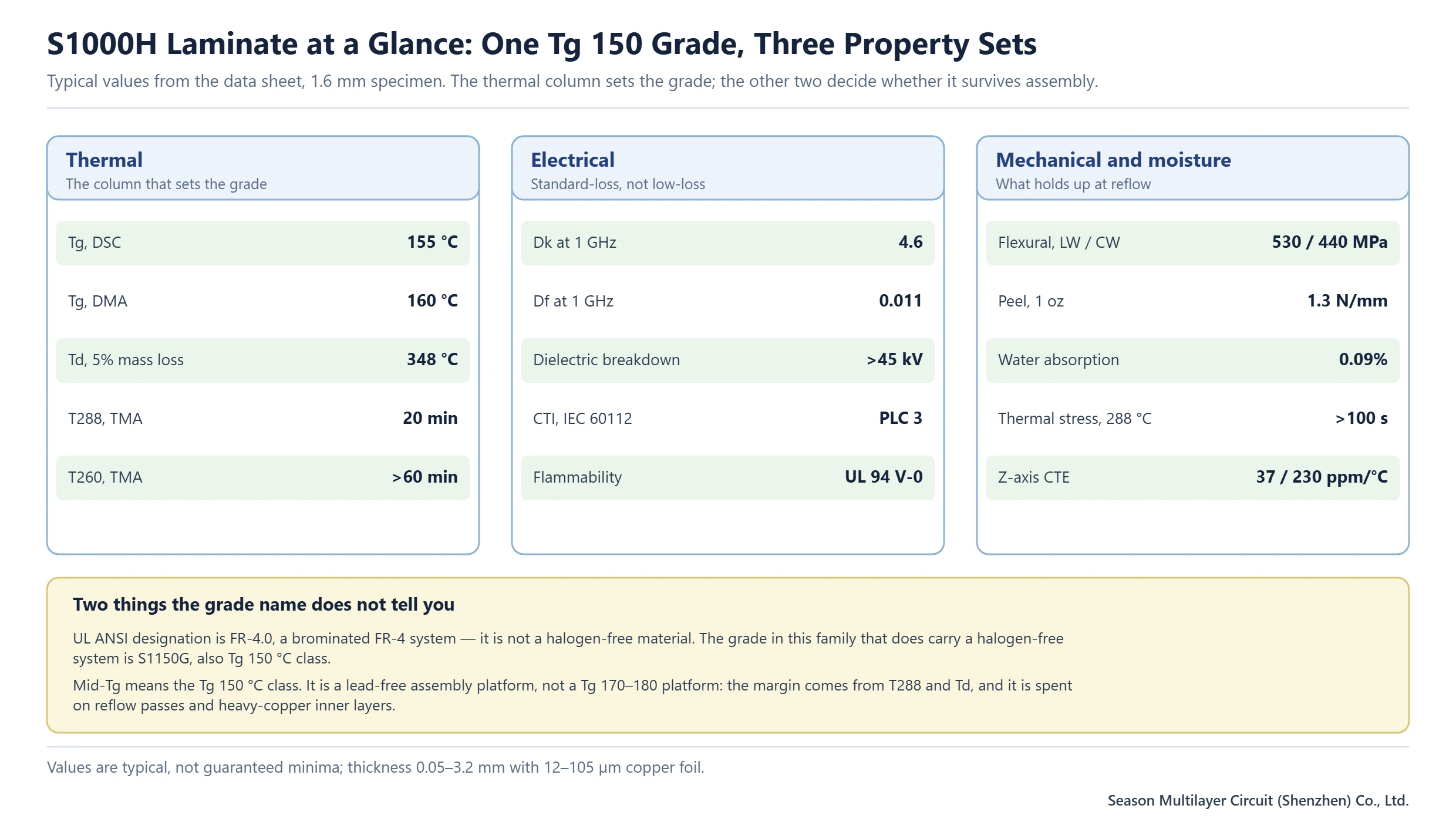
Most stackup arguments about S1000H laminate start and end with one number: Tg 150. That number is correct and almost useless on its own. Two boards built on the same grade can behave completely differently in reflow and in thermal cycling, because what separates a surviving build from a delaminated one is the delamination time at 288 °C, the decomposition temperature, and how much water the laminate absorbed before it went into the press.
This page reads the grade the way a fabricator and a hardware engineer read it together: what the data sheet guarantees and what it merely indicates, which assembly routes the thermal numbers actually cover, where the electrical performance stops being good enough, and the specific requirement that forces you off this grade and onto another one. It also settles the one claim that circulates most often and is wrong — this is a brominated system, not a halogen-free one.
Table of Contents
- What S1000H Laminate Is, in Fabrication Terms
- Reading the S1000H Laminate Data Sheet Without Over-Reading It
- Thermal Margin Comes From T288 and Td, Not From Tg
- The Electrical Position: Standard-Loss, and Priced Accordingly
- Anti-CAF and Moisture: The Actual Reason the Grade Exists
- The Brominated Question: When You Need S1150G Instead
- Where It Fits Against Tg 170 and Tg 180 Grades
- Process Notes: Drilling, Lamination and Surface Finish
- Ordering Checklist Before You Release the Stackup
- FAQ
- Have the Stackup Reviewed Against the Assembly Route
What S1000H Laminate Is, in Fabrication Terms
S1000H laminate is a woven-glass, epoxy-based FR-4 system carrying a UL ANSI designation of FR-4.0, with a reference specification sheet of IPC-4101/99 and a Tg in the 150 °C class. It is supplied from 0.05 mm to 3.2 mm with 12 µm to 105 µm copper foil, and it is bonded with its own prepreg, S1000HB, in glass styles from 106 through 7628. On a shop floor that means a normal FR-4 process window: standard desmear, standard plating chemistry, standard lamination cycle. Nothing about the material requires a special line.
Its positioning inside the family is the useful part. It sits one step above general-purpose FR-4, which typically lands in the 130–140 °C Tg band, and one step below the Tg 170 and Tg 180 grades. The step it buys is not signal performance; it is the ability to take lead-free assembly and repeated rework without the laminate moving under the barrel. That is why the grade appears most often in industrial control, power supply, appliance and instrument boards rather than in anything with a controlled-impedance high-speed bus.
It is worth being explicit about what the grade is not, because both points are commonly mis-stated. It is not a low-loss material, and it is not a halogen-free material. Both limits are covered further down with the numbers behind them.
Reading the S1000H Laminate Data Sheet Without Over-Reading It
Data sheet numbers are typical values on a 1.6 mm specimen built from eight plies of 7628 glass, tested to IPC-TM-650 methods. They are a design input, not a purchase guarantee: a 0.4 mm core and a 3.2 mm backplane built from the same chemistry will not return the same numbers, and Tg in particular is only quoted for specimens at or above 0.5 mm. When a customer specification has to be met rather than approximated, the conversation moves to the laminate supplier’s certificate of conformance for the lot, not to the marketing data sheet.
| Property | Test method | Condition | Typical value | What it actually decides |
|---|---|---|---|---|
| Tg | IPC-TM-650 2.4.25D | DSC | 155 °C | Whether the 150 °C class claim holds |
| Tg | IPC-TM-650 2.4.24.4 | DMA | 160 °C | The number a thermal model usually wants |
| Td | IPC-TM-650 2.4.24.6 | TGA, 5% mass loss | 348 °C | Headroom above the reflow peak |
| T288 | IPC-TM-650 2.4.24.1 | TMA | 20 min | Delamination resistance during rework |
| T260 | IPC-TM-650 2.4.24.1 | TMA | >60 min | How many assembly passes it survives |
| Z-axis CTE | IPC-TM-650 2.4.24 | Before / after Tg | 37 / 230 ppm/°C | Barrel strain per thermal cycle |
| Dk / Df | IPC-TM-650 2.5.5.9 | 1 GHz | 4.6 / 0.011 | Impedance target and insertion loss |
| Water absorption | IPC-TM-650 2.6.2.1 | D-24/23 | 0.09% | CAF risk and the pre-lamination bake |
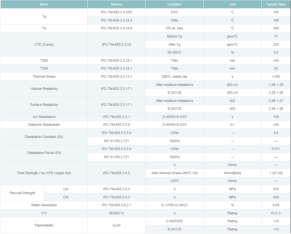
Two rows in that table are worth more attention than the rest. The thermal stress entry — more than 100 s in a 288 °C solder dip with no delamination — is the one an incoming inspection actually repeats, because it fails loudly and quickly. The CTE pair is the one that quietly decides long-term via reliability: 37 ppm/°C below Tg is a reasonable match to copper, but 230 ppm/°C above Tg means that every excursion past 150 °C loads the barrel in tension.
Thermal Margin Comes From T288 and Td, Not From Tg
Tg is a transition, not a limit. Above it the laminate does not melt; it expands at roughly six times the sub-Tg rate and loses stiffness. The practical consequences — barrel cracking, pad lifting, measling — are governed by how long the material can sit above that temperature before the resin-to-glass bond gives up. For this grade that is 20 minutes at 288 °C, with a decomposition temperature of 348 °C, which is 88 °C above a typical lead-free reflow peak.
| Assembly route | Relevant data sheet limit | Verdict |
|---|---|---|
| Single-sided reflow, lead-free | T288 20 min, Td 348 °C | Comfortable margin |
| Double-sided reflow plus one rework pass | T288 20 min | Within the data sheet, but track cumulative time above 217 °C |
| Heavy copper inner layers, repeated solder float | Thermal stress >100 s at 288 °C | Supported; confirm the press cycle at engineering review |
| Selective solder with extended preheat | T288 20 min | Review the profile before release, not after |
The useful habit is to count reflow exposures rather than to look up Tg. A double-sided assembly with one rework event is three excursions above the reflow liquidus, and the third one is where a marginal profile starts to show as measling around the through-holes. If the board also carries 4 oz inner layers, the thermal mass raises the dwell time at peak and eats the same margin faster.
- Count the excursions above 217 °C before quoting the grade, not the number of components.
- Ask for the actual press cycle used for the lot; cure time below 180 °C shortens the margin that the data sheet advertises.
- Bake panels before lamination if they have been stored outside the supplier’s humidity envelope.
- If two or more rework events are expected by contract, design the thermal margin in rather than relying on operator discipline.
The Electrical Position: Standard-Loss, and Priced Accordingly
At 1 GHz the grade measures Dk 4.6 and Df 0.011. For impedance control that is entirely workable — 50 Ω and 100 Ω differential geometries are routine, and the design rules are the same ones used for any FR-4 system. What it does not support is loss-controlled routing: on a long run, 0.011 of dissipation factor turns into insertion loss that a low-loss laminate would halve or better, which is why every serious loss budget ends up choosing between this class and a dedicated low-loss material rather than trying to tune this one.
The other electrical number that gets misused is CTI. This grade measures PLC 3 under IEC 60112, which is the 175–249 V band. That is a normal result for standard FR-4 and it is not a high-CTI material: if the product needs 600 V of tracking resistance across a narrow gap, the answer is a different laminate with a PLC 1 or PLC 0 rating and more creepage, not a thicker solder mask. The laminate selection guide covers how that choice interacts with board thickness and copper weight.
Dielectric breakdown above 45 kV and volume resistivity of 1.5 × 10⁸ MΩ·cm are the numbers to quote when the application is a power supply rather than a logic board, because they are what the safety review asks for. Neither changes with layer count; both change with moisture, which is the next problem.
Anti-CAF and Moisture: The Actual Reason the Grade Exists
Conductive anodic filament growth is a electrochemical failure, not a mechanical one: under bias, in a humid environment, copper migrates along the resin-to-glass interface from an anode to a cathode and eventually shorts two nets that were designed to be isolated. It needs three things at once — moisture, voltage, and a continuous interface to travel along. The anti-CAF resin system in this grade attacks the third condition, and 0.09% water absorption reduces the first.
Where it shows up in practice is dense via fields in thin dielectric, especially where a via pair sits at different potentials with less than 0.3 mm of resin between them, and where the board lives in an enclosure that cycles between warm and cold. Designers who have been bitten once usually add three things to the rule set: keep the dielectric between opposite-polarity vias above the minimum the fabricator will sign for, stagger the via field so the fibres do not line up into a continuous path, and spec a bake before lamination so the prepreg goes into the press dry.
This is also the reason the grade is a common choice for instrument and industrial boards that will never see a controlled-impedance requirement. The value is not in the electrical numbers; it is in the fact that the board is still isolating after five years in a humid cabinet.
The Brominated Question: When You Need S1150G Instead
The UL ANSI designation FR-4.0 is the tell. That classification describes a brominated FR-4 system, and bromine is the flame retardant doing the work behind the UL 94 V-0 rating. Boards that carry this designation are therefore not free of halogen, regardless of how the marketing page reads. If a customer specification, a procurement restriction or an end-market regulation bans brominated flame retardants, this grade is out of scope before any technical discussion starts.
The grade to specify in that case is S1150G, which uses a phosphorus-based system with no bromine and no antimony, keeps the Tg at 150 °C or above, and carries a UL FR-4.1 designation. Electrically and mechanically it is close enough that the stackup rarely changes; the lamination window and the prepreg handling do, and that is a fabricator conversation rather than a design one. The halogen-free laminate guide for S1150G has the process detail.
The mistake to avoid is treating the two as interchangeable and letting procurement decide on availability. They are not interchangeable on paper, and the certificate of conformance will say so. Decide on the chemistry first, then on the grade.
Where It Fits Against Tg 170 and Tg 180 Grades
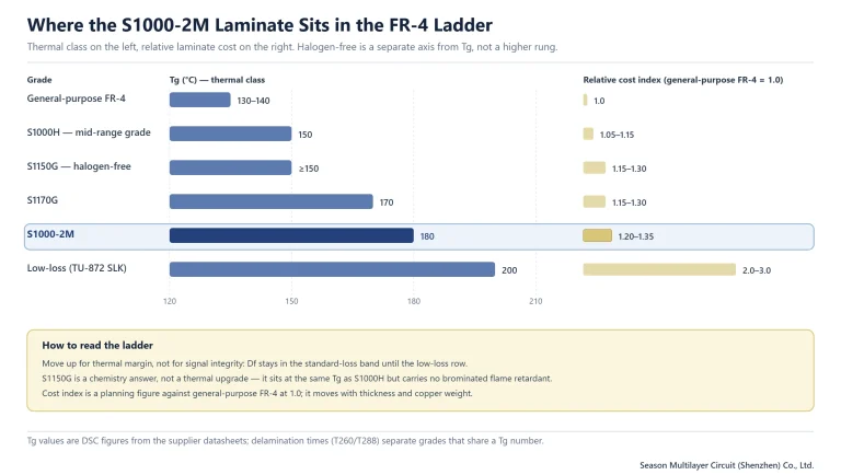
Stepping up a thermal class is a cost decision that should be justified by a requirement, not by comfort. The three grades above this one in the same family differ mainly in where the transition sits and how much delamination time they buy; the electrical performance of the brominated members stays in the standard-loss band until you leave the family entirely.
| Grade | Tg class | Chemistry note | Relative cost index | Pick it when |
|---|---|---|---|---|
| General-purpose FR-4 | 130–140 °C | Brominated | 1.0 | No lead-free assembly, no thermal cycling |
| S1000H | 150 °C (mid) | Brominated, FR-4.0 | 1.05–1.15 | Lead-free assembly, humid environment, dense vias |
| S1150G | ≥150 °C | No bromine | 1.15–1.30 | The same duty, with bromine banned |
| S1170G | 170 °C | Brominated | 1.15–1.30 | Service temperature above 105 °C, or a thicker board |
| S1000-2M | 180 °C | Brominated, FR-4.0 | 1.20–1.35 | High layer count, repeated rework, automotive body electronics |
| Low-loss class (TU-872 SLK) | 200 °C | Low-loss system | 2.0–3.0 | Loss-controlled nets, not thermal need |
The cost column is a planning index against general-purpose FR-4 at 1.0; it moves with thickness, copper weight and order quantity, and it should be confirmed on a quotation rather than modelled. What does not move is the shape of the curve: the step from 150 °C to 170 °C is small, and the step from any thermal grade to a low-loss grade is large. That asymmetry is the reason an engineer who only needs thermal margin should never pay for loss performance.
The comparison most customers actually ask for is against S1000-2M, the Tg 180 grade. Same chemistry family, same brominated system, 30 °C more transition and a longer delamination time. Choose it when the board will see more than two rework passes, when the service temperature genuinely exceeds 105 °C, or when the layer count makes Z-axis expansion the dominant failure mode. Choose this grade when none of that is true, because the difference is money that buys nothing.
Process Notes: Drilling, Lamination and Surface Finish
Drilling is unremarkable in a good way: carbide bits, controlled hit counts, proper entry and exit material. The limit that matters is aspect ratio, and a 12:1 ratio is routine while 20:1 should be quoted as a review item rather than assumed. Hole walls at that depth need adequate desmear before metallisation, and the anti-CAF chemistry does not compensate for a smeared wall. The drilling process comparison sets out where mechanical drilling gives way to laser for blind structures.
Lamination follows the supplier’s press cycle: cure above 45 minutes in the 180–190 °C window, with the heat-up rate adjusted for inner-layer copper and stackup. The prepreg that bonds this core is S1000HB, available in 106, 1080/1078, 2313/3313, 2116, 1506 and 7628 styles with resin contents from 46% to 78%. Thin styles cure to 0.05 mm and the heavy styles to 0.225 mm, which is what makes a 0.05 mm to 3.2 mm finished thickness range achievable without changing chemistry.
Surface finish does not interact with the laminate choice in any meaningful way: HASL, ENIG, OSP and immersion silver all run on this grade with standard parameters. What does interact is the number of thermal excursions the finish adds — hot-air levelling is one more trip above liquidus, and on a heavy board that is the one to count. The surface finish comparison covers the trade-offs without repeating them here.
Ordering Checklist Before You Release the Stackup
Most of the expensive mistakes on a mid-Tg build happen at the quotation stage, where a grade gets substituted for availability and nobody re-checks the requirement it was chosen for. Six items close that gap.
- State the grade and the Tg class separately, and state the chemistry: brominated or bromine-free. A grade name alone is ambiguous across suppliers.
- Give the finished thickness and the copper weight per layer, not the core thickness, so the prepreg build can be checked against the press cycle.
- Say how many reflow exposures the assembly will see, including rework, and whether any of them are hot-air levelling.
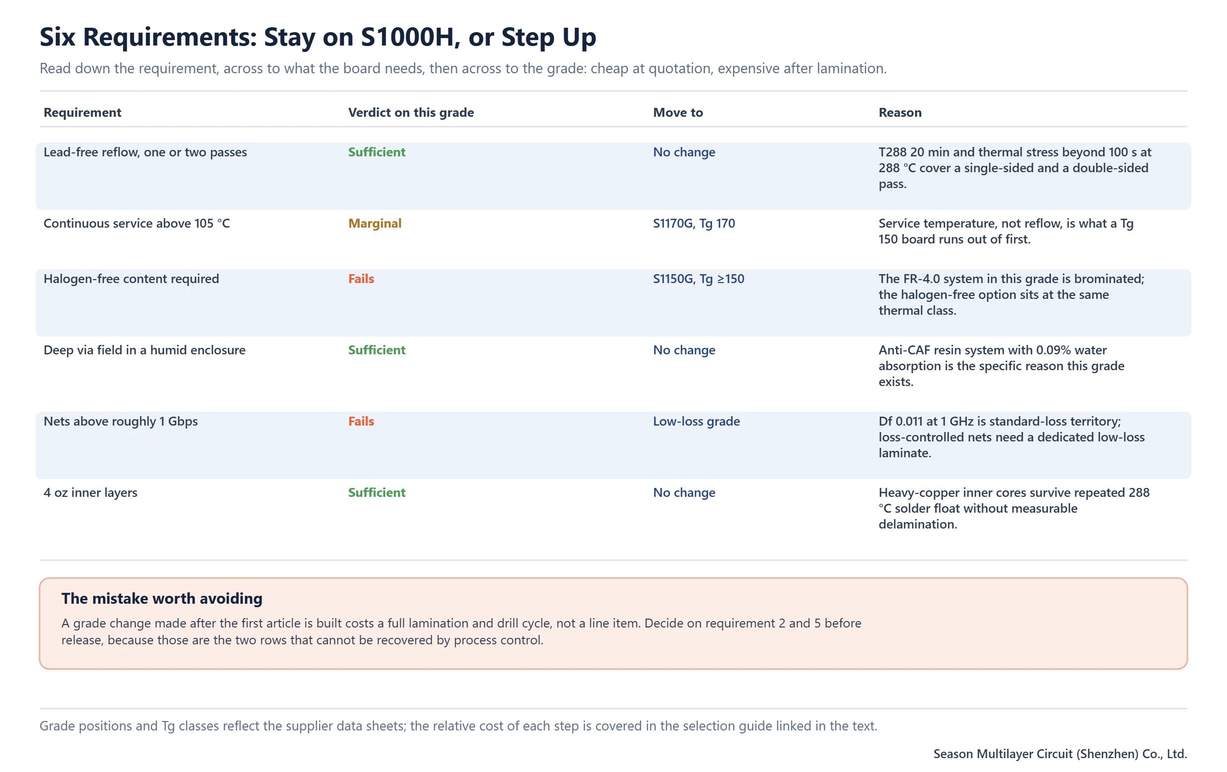
- Confirm the maximum service temperature, because that is the requirement that actually moves a design from this grade to the Tg 170 grade.
- State the surface finish and the maximum time between fabrication and assembly, which sets the bake and packaging requirement.
- If humidity or bias is part of the environment, say so: the via-to-via spacing rule and the anti-CAF claim only mean something when the application is described.
The laminate is the cheapest place to be correct and the most expensive place to be wrong. A grade substitution after the first article is a full lamination and drill cycle; a grade decision made at quotation costs nothing but the time to read the requirement.
Frequently Asked Questions
Is the S1000H laminate brominated?
No. Its UL ANSI designation is FR-4.0, which describes a brominated FR-4 system, so bromine is present as the flame retardant behind the UL 94 V-0 rating. When a specification bans brominated flame retardants, the grade in the same family to use instead is S1150G, which keeps the Tg at 150 °C or above and carries a UL FR-4.1 designation.
What is the Tg of S1000H laminate?
The Tg 150 °C class is the specification claim. Typical measured values run slightly above that: 155 °C by DSC and 160 °C by DMA on a 1.6 mm specimen. Tg is only quoted for specimens 0.5 mm or thicker, which is one of the reasons a thin core and a thick backplane should not be assumed to return the same number.
Does S1000H laminate work with lead-free reflow?
Yes. Lead-free compatibility is the reason the grade exists: T288 is 20 minutes, T260 is above 60 minutes, Td is 348 °C and thermal stress exceeds 100 s in a 288 °C solder dip without delamination. What the data sheet does not do is count your excursions, so track the number of passes above liquidus, including rework.
Can I use S1000H laminate for 1 Gbps and faster signals?
Not for loss-controlled routing. Df is 0.011 and Dk is 4.6 at 1 GHz, which is standard-loss territory. Impedance control works fine at those values, but a long high-speed run needs a dedicated low-loss laminate where Df drops into the 0.009 range or below. Paying for a low-loss grade is only justified when the loss budget demands it.
What thickness and copper weight can I order?
The purchasing range is 0.05 mm to 3.2 mm finished thickness with copper foil from 12 µm to 105 µm, in standard panel sizes from 915 × 1,220 mm to 1,070 × 1,220 mm. Other sizes and thicknesses are available on request, which in practice means quoting them rather than assuming them.
Is S1000H laminate a high-CTI material?
No. It measures PLC 3 under IEC 60112, the 175–249 V band, which is normal for standard FR-4. If the design needs 600 V of tracking resistance across a narrow gap, the correct answer is a laminate with a PLC 1 or PLC 0 rating plus additional creepage, not more solder mask or a thicker board.
What is the difference between S1000H and S1000-2M?
Both are brominated FR-4.0 systems in the same family; the difference is the thermal class. S1000H sits at Tg 150 °C with T288 of 20 minutes, while S1000-2M sits at Tg 180 °C with a longer delamination time. Move up when service temperature exceeds 105 °C, when more than two rework passes are expected, or when high layer count makes Z-axis expansion dominant.
Have the Stackup Reviewed Against the Assembly Route
Send the Gerber data, the layer stack and the assembly route — including how many reflow passes and rework events the product will see. Engineering will confirm the grade against those requirements and flag where a different thermal class or a low-loss material is the cheaper decision in the long run. Multilayer builds from 2 to 30 layers are supported in volume, with sample quantities up to 64 layers reviewed case by case.
The PCB materials and laminates reference covers the rest of the family, and the manufacturing services overview sets out how lamination, drilling and surface finish are scheduled together.