Book Appointment Now

14-Layer Computing PCB
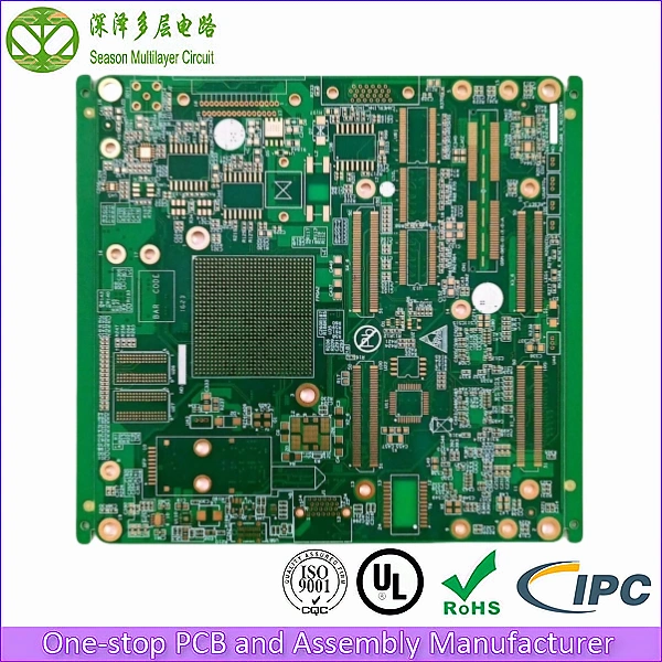
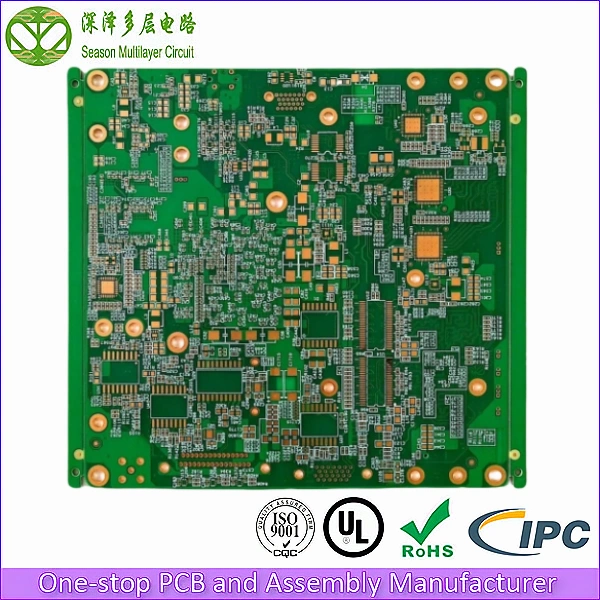
Ultra-high-density 14-layer computing PCBs for high-performance computing platforms, AI accelerators, and edge computing systems with multi-gigabit memory interfaces, dense BGA routing, and advanced thermal management for sustained compute workloads.
High-performance computing systems demand PCBs that can route multi-gigabit memory interfaces (DDR5, HBM), PCIe Gen5 links, and dense BGA fanouts — all while managing extreme thermal loads from power-hungry processors. At Season PCB, we manufacture 14-layer computing PCBs with HDI technology, back-drilling, and heavy copper thermal management for AI, data center, and edge computing applications.
14
Layer Count
3/3 mil
Min. Trace/Space
0.10 mm
Min. Via Diameter
Tg 180
Glass Transition Temp
1–2 µ”
ENIG Gold Thickness
ISO 9001:2015
ISO 14001
UL (E305905)
IPC Class 2 / Class 3
RoHS
IATF16949
Table of Contents
14-Layer Computing PCB Stackup Diagram
Our standard 14-layer computing PCB stackup is built around three requirements of high-performance computing boards: every high-speed net must see a solid reference plane, every voltage domain must have its own low-impedance plane pair, and the finished board must still be manufacturable at high yield. The stackup therefore puts DDR5 and HBM memory channels, PCIe Gen5 links and SerDes lanes on inner signal layers sandwiched between ground planes, separates core, memory and I/O power onto dedicated planes, and keeps a five-plane ground system throughout. This is the build-up we use for AI accelerator cards, server motherboards and edge computing platforms.
| L1 (Top) | Signal – outer copper | CPU/GPU BGA, DDR5/HBM escape routing, high-speed I/O | 40 um plated copper (foil + plating) |
| L2 | Ground plane | Reference for L1 memory signals | Keep high-speed nets clear of plane splits |
| L3 | Signal – inner, 18 um | DDR5/DDR4 memory interface routing | Routed against L2/L4, length-matched |
| L4 | Ground plane | Signal reference and EMI shielding | Stitched to L2/L7 with via arrays |
| L5 | Signal – inner, 18 um | PCIe Gen4/Gen5 differential pair routing | 100 ohm differential, back-drilled vias |
| L6 | Power plane – VCORE | Core voltage distribution | Paired with L7 for buried capacitance |
| L7 | Ground plane | Power reference and thermal spreader | Thermal via arrays under the processor |
| L8 | Power plane – VDDQ | Memory voltage and I/O power | Paired with L7/L9 |
| L9 | Ground plane | Reference for L10 SerDes routing | Keeps SerDes return paths short |
| L10 | Signal – inner, 18 um | High-speed SerDes and networking interfaces | Back-drilled, 100 ohm differential |
| L11 | Signal – inner, 18 um | Low-speed control and management signals | Absorbs long routing to protect L3/L5/L10 |
| L12 | Ground plane | Bottom-side signal reference | Shields L13 from bottom-layer routing |
| L13 | Power plane | Auxiliary and I/O power distribution | Plane pair with L12 |
| L14 (Bottom) | Signal – outer copper | Bottom BGA routing and thermal pad | 40 um plated copper (foil + plating) |
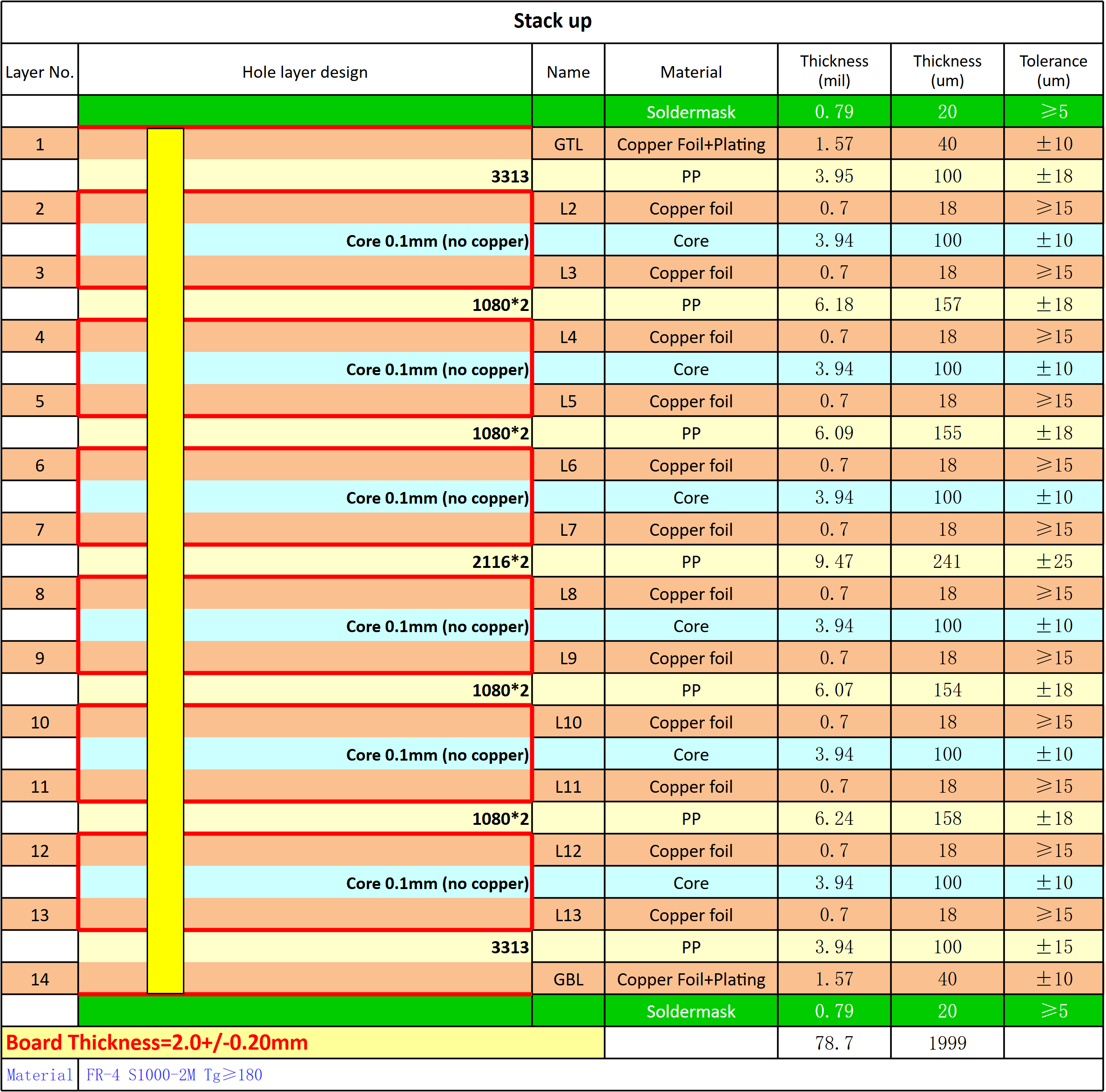
The 14-layer architecture provides five ground planes and three power planes, creating a low-impedance power delivery network (PDN) essential for high-performance processors. Back-drilling on signal vias enables multi-gigabit memory and PCIe signal integrity. The build-up uses 0.10 mm FR-4 cores with 18 um copper foil for the inner signal and plane pairs, 3313, 1080×2 and 2116×2 prepreg between cores, and 40 um plated outer copper on L1 and L14, for a finished thickness of 2.0 ±0.20 mm at Tg 180. That structure keeps the dielectric between each signal layer and its reference plane thin and uniform, which is what makes the impedance targets repeatable from panel to panel. The ENIG surface finish then ensures reliable soldering of fine-pitch BGA packages.
Stackup Design Rules We Apply to Every 14-Layer Build
- Reference every signal layer to an adjacent solid plane. L3 is referenced to L2/L4, L5 to L4/L7, L10 to L9/L12, so no high-speed net crosses a plane split or changes reference mid-route.
- Pair each power plane with ground for buried capacitance. L6-L7 carries VCORE and L8-L9 carries VDDQ, separated by thin dielectric to lower plane impedance across the whole power delivery network.
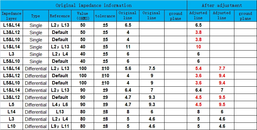
- Hold impedance to the released design table. Single-ended traces target 40/50 ohm at ±5% and differential pairs 80/90/100 ohm at ±8–10%, verified with a Polar Instruments report on every production batch.
- Minimise stub on multi-gigabit vias. Back-drilling is applied to DDR5, PCIe Gen4/Gen5 and SerDes vias, held to ±0.05 mm depth with a minimum achievable stub length of 0.10 mm.
- Use the ground planes as thermal copper. L4, L7, L9 and L12 spread heat away from the processor area and carry thermal via arrays through to the opposite side of the board.
- Keep the 14-layer computing PCB stackup rescalable. The same reference and impedance rules hold when the layer count moves between 12 and 16 layers for a different signal-to-plane budget.
When a 14-Layer Computing PCB Stackup Is the Right Choice
A 14-layer stackup earns its cost when a single board has to carry DDR5 memory at 6400+ MT/s, several PCIe Gen4/Gen5 links and 0.4 mm pitch BGA fanout at the same time while keeping enough plane pairs for a quiet power delivery network. If the design has fewer high-speed nets, a 10 or 12-layer stackup with the same reference rules will do the job at lower cost. If it adds more SerDes or memory channels, the architecture scales to 16 layers by inserting another signal-plus-plane pair without redesigning the plane system.
Technical Capability & Specifications
| Parameter | Specification | Advanced Capabilities |
|---|---|---|
| Layer Count | 14 Layer | 2-30L (Mass); 2-64L (Sample) |
| Base Material | FR-4 S1000-2M Tg 180 | SY, NY, TUC, ZY, EMC, KB, ITEQ, Rogers, Megtron, Nelco, Isola |
| Board Thickness | 2.0mm | 0.2-6.4mm (Mass); 0.15-20mm (Sample) |
| Panel Size | 200 × 180 mm (1-up) | 800×600mm (Mass); 1050×610mm (Sample) |
| Copper Thickness | Outer: 1 oz (foil + plating, 40 µm) Inner: 0.5 oz (18 µm foil) | Outer: 1/3–12 oz Inner: 1/4–12 oz |
| Min Drill Size | 0.10mm (Laser) | 0.075mm (Laser Sample) |
| Min Trace Width/Spacing | 3/3 mil | 2.5/2.5 mil (Sample) |
| Back-Drill | Available (±0.05mm) | Min stub: 0.10mm |
| Surface Finish | ENIG | ENIG, ENEPIG, OSP, Immersion Silver |
| Solder Mask | Customer-specified color | LPI (liquid photo-imageable), matte or gloss |
| Impedance Control | Single-ended 40/50 Ohm ±5% Differential 80/90/100 Ohm ±8–10% | Custom impedance targets on request |
| BGA Pitch Support | 0.4mm | 0.3mm (Sample) |
Key Advantages of Our 14-Layer Computing PCB
- 5-Ground-Plane PDN Architecture: Five dedicated ground planes create a low-impedance power delivery network, reducing power supply noise by 20dB+ for stable high-performance processor operation at sustained loads.
- HDI BGA Fanout Capability: 0.10mm laser-drilled blind vias with 3/3 mil trace/space enable dense fanout routing for 0.4mm pitch BGAs used in modern CPUs, GPUs, and AI accelerators.
- Back-Drilled Multi-Gigabit Channels: Back-drilling on signal vias eliminates stub reflections, enabling clean DDR5 and PCIe Gen4/Gen5 signal transmission at 16+ Gbps data rates.
- Multi-Domain Power Isolation: Separate power planes for core voltage (L6), memory voltage (L8), and auxiliary power (L13) prevent cross-domain noise coupling in mixed-voltage computing systems.
- Heavy Copper Thermal Option: Available 2-12 oz inner copper for thermal spreading under high-TDP processors, reducing junction temperatures by 15-20C compared to standard copper weights.
Overcoming Critical Challenges in High-Performance Computing Design
When sourcing PCBs for high-performance computing applications, engineers encounter three critical challenges. Here is how our engineering team eliminates them:
1. DDR5 Memory Signal Integrity at 6400+ MT/s
The Problem: DDR5 memory interfaces operate at 6400 MT/s and beyond, requiring precise impedance control, minimal crosstalk, and clean signal paths. Poor PCB design causes setup/hold violations, bit errors, and memory training failures that prevent system boot.
Our Solution: Our 14-layer stackup places DDR5 signal layers (L3) between dedicated ground planes (L2, L4) for optimal signal reference. Tight impedance control (40/50 ohm single-ended, 80–100 ohm differential) and length matching (within ±5mil) ensure clean memory signals. Back-drilled vias eliminate stub reflections at connector transitions.
2. Thermal Management for High-TDP Processors
The Problem: Modern AI accelerators and server CPUs dissipate 300-500W, creating extreme thermal density. Standard PCB copper weights cannot spread this heat effectively, causing local hotspots that degrade performance and trigger thermal throttling.
Our Solution: We offer heavy inner copper (up to 12 oz) on dedicated thermal layers connected to the processor via thermal via arrays. The multiple ground planes act as thermal spreaders, distributing heat across the board. For extreme thermal loads, we offer copper coin inlays for targeted heat extraction.
3. Dense BGA Fanout for 0.4mm Pitch Processors
The Problem: Modern CPUs and AI accelerators use 0.4mm pitch BGA packages with thousands of pins. Routing escape patterns from these dense arrays requires HDI technology that conventional PCBs cannot provide.
Our Solution: Our HDI process with 0.10mm laser-drilled blind vias and 3/3 mil trace/space enables full fanout of 0.4mm pitch BGAs. Via-in-pad technology (with resin fill and copper planarization) places interconnects directly under BGA pads, maximizing routing channels. For 0.3mm pitch, we offer 0.075mm laser microvias.
Where Our Computing PCBs Are Used
Our 14-layer computing PCBs power a wide range of high-performance computing applications:
- AI Accelerator Cards: GPU/TPU accelerator boards with PCIe Gen5 interfaces for machine learning training and inference in data centers.
- Edge Computing Platforms: Compact edge servers with AI inference capability for industrial IoT, smart cities, and autonomous systems.
- Server Motherboards: High-density server motherboards with multi-socket CPU configurations, DDR5 memory, and PCIe expansion.
- Network Processing Units: High-throughput network processing boards with 100/400G Ethernet and hardware-accelerated packet processing.
- High-Performance Storage Controllers: NVMe SSD controller boards with PCIe Gen4/Gen5 interfaces for enterprise storage systems.
Our Quality Commitment for Computing PCBs
High-performance computing electronics demand exceptional signal integrity and thermal reliability. We implement rigorous testing protocols on every 14-layer computing PCB:
- 100% AOI Inspection: Automated Optical Inspection scans every layer for trace breaks, shorts, and alignment errors.
- 100% Electrical Testing (E-Test): Fixture-based testing with high-density probe arrays for BGA pin verification.
- Controlled Impedance Testing: Polar Instruments test report documenting single-ended and differential impedance compliance.
- Back-Drill Verification: Cross-section inspection of back-drilled via stub length on sample boards.
- Certifications: ISO 9001:2015, ISO 14001, UL (E305905), RoHS compliant. IPC Class 3 available for enterprise computing.
Why Choose Season PCB for Your Computing PCB?
With PCB manufacturing experience dating back to 2006, Season PCB builds high-performance computing PCBs for data center, telecommunication, and AI accelerator programs, with capacity for both rapid prototyping and volume production.
We understand that high-performance computing electronics demand exceptional signal integrity and thermal management. That is why every 14-layer computing PCB we ship is backed by:
- Free DFM file checking before production — including signal integrity review
- Dedicated engineering support throughout production
- Reliable delivery scheduling
- Flexible volumes matched to your program stage
- Engineering fee waivers on bulk production orders
Season PCB specializes in 14-layer computing PCB manufacturing for AI accelerators, high-performance computing platforms, and edge computing systems. Our computing PCB products feature 5-ground-plane PDN architecture, HDI BGA fanout, and back-drilled multi-gigabit channels. We also manufacture high-speed backplane PCBs and 10-layer M.2 SSD PCBs for computing applications. Each computing PCB meets IPC standards.
For your 14-layer computing PCB needs, Season PCB provides fast turnaround, competitive pricing, and ISO-certified quality. Explore our PCB manufacturing capabilities or contact us for computing PCB manufacturing today.
Our computing PCB boards comply with UL safety certifications, IPC manufacturing standards, and JEDEC memory specifications for DDR5 and HBM. Each computing PCB undergoes signal integrity testing per IEEE standards and thermal verification. Volume programmes of this build run on 998PCB Group’s 2–30 layer PCB lines under the same quality system.
Frequently Asked Questions
What BGA pitch sizes can your 14-layer PCBs support?
Our standard HDI process supports 0.4mm pitch BGAs using 0.10mm laser-drilled blind vias with 3/3 mil trace/space. For sample production, we can support 0.3mm pitch using 0.075mm laser microvias and 2.5/2.5 mil trace/space. Via-in-pad technology is available for maximum routing density.
Can you provide back-drilling on 14-layer boards?
Yes, we provide controlled-depth back-drilling with ±0.05mm depth accuracy. Minimum achievable stub length is 0.10mm. Back-drilling is recommended for all multi-gigabit signal vias (DDR5, PCIe Gen4/Gen5, SerDes) to eliminate stub-induced signal reflections.
How long does a 14-layer computing PCB prototype take?
A 14-layer computing PCB goes through multiple sequential lamination cycles, with back-drilling and impedance verification after each press, and every additional lamination pass adds its own queue cycle. Because the schedule depends on current line loading and on how many passes your stackup needs, we confirm the production window for each order at quotation rather than publishing a fixed number here.
What materials and processes are available for 14-layer computing PCBs?
The standard 14-layer computing PCB build is FR-4 S1000-2M (Tg 180) at 2.0mm board thickness, with SY, NY, TUC, ZY, EMC, KB, ITEQ, Rogers, Megtron, Nelco, and Isola laminates available. Copper is 1 oz outer (foil + plating) and 0.5 oz inner foil, expandable to 12 oz. Minimum laser drill is 0.10mm with 3/3 mil trace width and spacing, and back-drilling is held to ±0.05mm with a minimum stub of 0.10mm.
ENIG is the standard surface finish, with ENEPIG, OSP, and immersion silver optional. Solder mask color is customer-specified, in LPI with matte or gloss finish. Controlled impedance covers single-ended 40/50 ohm (±5%) and differential 80/90/100 ohm (±8–10%), and BGA pitch support starts at 0.4mm.
How do you verify quality on 14-layer computing PCBs?
Every 14-layer computing PCB passes 100% AOI, which scans each layer for trace breaks, shorts, and alignment errors, plus 100% electrical testing on fixture-based systems with high-density probe arrays for BGA pin verification. A Polar Instruments impedance test report documenting single-ended and differential impedance compliance accompanies every batch, and cross-section inspection verifies back-drilled via stub length on sample boards. We are certified to ISO 9001:2015, ISO 14001, UL (E305905), and RoHS, with IPC Class 3 available for enterprise computing.
Ready to start your Computing PCB project?
Whether your program calls for early prototype builds or full-volume production, our engineering team is ready to support your computing PCB project with DFM review, signal integrity analysis, and fast-turn fabrication.
Tel: (+86) 18681528532 | WhatsApp: +86 18681528532
E-mail: roc@season-pcb.com