Book Appointment Now

Double-Sided Medical FPC
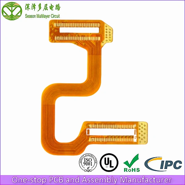
Medical-grade flexible PCBs (FPC) — custom medical FPC manufacturing for wearable medical devices, patient monitoring sensors, and implantable electronics. Ultra-thin, reliable, and engineered for the rigorous demands of medical applications.
Medical devices increasingly rely on flexible printed circuits (FPC) to achieve the compact, lightweight, and conformable form factors required for wearable health monitoring, surgical instruments, and implantable devices. At Season Multilayer Circuit, we manufacture double-sided medical FPCs with medical-grade polyimide materials, precision impedance control, and ISO 9001:2015 certified quality processes for the medical device industry.
2
Layer Count
3/3 mil
Min. Trace/Space
0.10 mm
Min. Via Diameter
PI 25 µm
Polyimide Thickness
1-2 u”
ENIG Gold Thickness
ISO 9001:2015
ISO 14001
UL (E305905)
IPC Class 2 / Class 3
RoHS
Table of Contents
Double-Sided Medical FPC Stackup Diagram
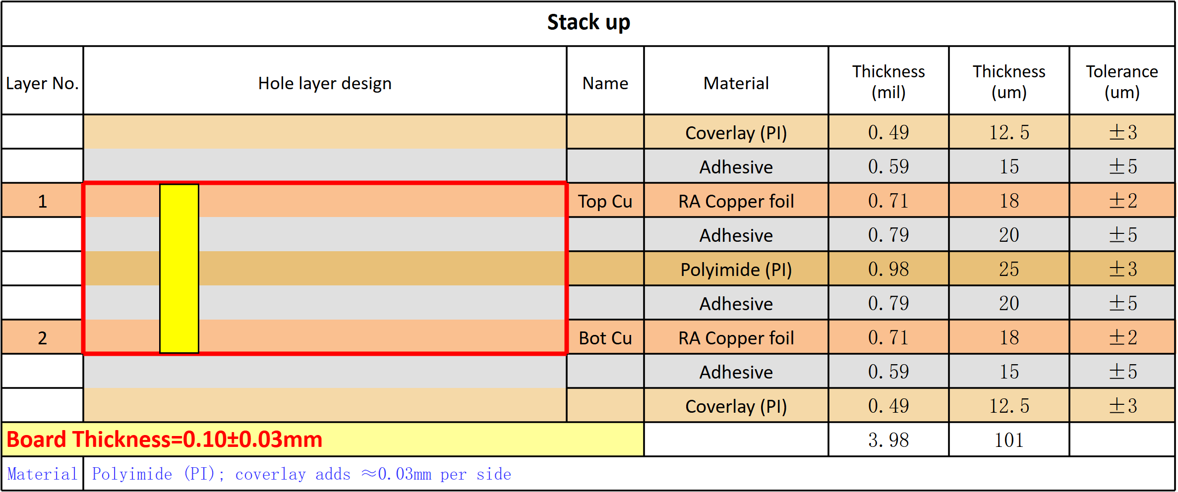
Our double-sided medical FPC stackup uses medical-grade polyimide substrate with copper on both sides, providing flexible routing capability for compact medical device electronics that must conform to body contours or fit within miniature device housings.
- Top Layer (Copper): Component placement, sensor pads, electrode contacts
- Adhesive Layer: Medical-grade acrylic adhesive bonding copper to polyimide
- Polyimide Core (25 µm): Flexible insulating substrate providing mechanical support
- Adhesive Layer: Medical-grade acrylic adhesive bonding copper to polyimide
- Bottom Layer (Copper): Bottom routing, ground plane, shielding
- Coverlay (PI 12.5 µm): Protective polyimide coverlay with exposed pad openings
For implantable-grade applications, polyimide substrates are available with suppliers’ ISO 10993 biocompatibility test data. Our engineering team can customize the stackup thickness, copper weight, and coverlay configuration for your specific medical device requirements.
Technical Capability & Specifications
| Parameter | Specification | Advanced Capabilities |
|---|---|---|
| Layer Count | 2 Layer FPC | 1-8L (Mass); 1-10L (Sample) |
| Base Material | Polyimide (PI) 25 µm | PI 12.5/25/50/75 µm, PET |
| Board Thickness | 0.10mm | 0.05-0.30mm (FPC) |
| Panel Size | 60x40mm | 300x250mm (FPC Mass) |
| Copper Thickness | 1/2 oz (18 µm) | 1/3 oz (12 µm) to 2 oz (70 µm) |
| Min Drill Size | 0.10mm | 0.075mm (Sample) |
| Min Trace Width/Spacing | 3/3 mil | 2/2 mil (Sample) |
| Via Type | Through-hole (PTH) | Blind via, staggered microvia |
| Surface Finish | ENIG | ENIG, OSP, Immersion Silver, Tin |
| Coverlay | PI 12.5 µm | PI 12.5/25/50 µm, solder mask |
| Stiffener | PI/Stainless/FR4 | PI, Stainless steel 0.1-0.3mm, FR4 0.2-1.6mm |
| Flexibility | Dynamic/Static | Dynamic (100K+ cycles), Static |
Key Advantages of Our Medical FPC
- Medical-Grade Biocompatibility: Polyimide substrate and coverlay materials are available with suppliers’ ISO 10993 test data for skin contact and short-term implantable applications.
- Ultra-Thin Profile: 0.10mm base stackup enables integration into wearable patches, catheter-based devices, and miniature electronics where rigid PCBs cannot fit.
- Dynamic Flexibility: Tested for 100,000+ flex cycles for wearable applications requiring repeated bending, such as wrist-worn monitors and smart clothing sensors.
- Precision Sensor Integration: 3/3 mil trace/space enables fine-pitch electrode arrays for ECG, EEG, and EMG sensing directly on the FPC substrate.
- EMI Shielding Option: Bottom-side copper plane provides EMI shielding for sensitive biopotential measurement circuits, reducing noise in critical patient monitoring signals.
Overcoming Critical Challenges in Medical FPC Design
When sourcing flexible PCBs for medical device applications, engineers encounter three critical challenges. Here is how our engineering team eliminates them:
1. Biocompatibility and Material Safety
The Problem: Medical devices that contact skin or are implanted require biocompatible materials. Standard FPC materials may leach chemicals or cause allergic reactions, failing FDA biocompatibility testing and delaying device approval.
Our Solution: We work with medical-grade polyimide substrates and acrylic adhesives available with suppliers’ ISO 10993-5 (cytotoxicity), ISO 10993-10 (sensitization), and ISO 10993-23 (irritation) test data. For implantable-grade applications, USP Class VI certified material options are available with full traceability documentation.
2. Flex Fatigue in Wearable Applications
The Problem: Wearable medical devices are subject to repeated bending during daily wear. Standard FPCs develop cracks in copper traces after thousands of flex cycles, causing intermittent connections and device failure.
Our Solution: Our dynamic FPC design uses optimized copper grain structure, proper trace routing (per IPC-2223), and neutral axis placement to minimize flex stress. We test to 100,000+ flex cycles at specified bend radius. For critical applications, we offer rolled-annealed copper with superior flex fatigue resistance.
3. Miniaturization for Compact Medical Devices
The Problem: Miniaturized medical devices — including implantable-grade electronics — require extremely small, lightweight FPCs that fit within hermetically sealed housings. Standard PCB technology cannot achieve the required density.
Our Solution: Our 3/3 mil trace/space capability with 0.10mm microvias enables high-density routing on ultra-thin (0.05mm) polyimide substrates. Stiffeners are selectively applied only where components are mounted, keeping the rest of the FPC ultra-flexible for conformable routing within the device.
Where Our Medical FPCs Are Used
Our double-sided medical FPCs are deployed across a wide range of medical device applications:
- Wearable Patient Monitors: Continuous ECG, SpO2, and temperature monitoring patches with wireless connectivity for remote patient monitoring.
- Implantable-Grade Devices: Ultra-thin, lightweight FPCs for implantable-grade electronics where footprint, weight, and long-term reliability are critical.
- Medical Imaging Probes: Ultrasound transducer arrays and endoscope camera modules with high-density interconnects on flexible substrates.
- Surgical Instruments: Smart surgical tools with integrated force sensors, temperature monitoring, and LED illumination on conformable FPCs.
- Drug Delivery Systems: Micropump controllers and sensor arrays for wearable insulin delivery and transdermal drug delivery patches.
Materials and Coverlay Options for Medical FPC
Material selection sets the ceiling on everything a flex circuit can do — bend life, temperature rating, and long-term reliability in the field. Our standard medical FPC builds use polyimide film at 25 µm, and the same platform spans 12.5 µm for ultra-thin wearable patches up to 75 µm for designs that need extra mechanical robustness. PET is available as a lower-cost option for static consumer health products where dynamic bending is not required.
Copper choice matters just as much. Electrodeposited (ED) copper keeps costs down for static applications, while rolled-annealed (RA) copper — with its horizontal grain structure — delivers significantly longer dynamic flex life. For coverlay, we bond PI film at 12.5/25/50 µm over the finished circuitry; solder mask is available for designs that combine flexible and rigidized zones.
Stiffeners complete the mechanical design. PI, stainless steel (0.1–0.3 mm), and FR-4 (0.2–1.6 mm) stiffeners reinforce connector pads and component islands while leaving the active bend regions untouched — the approach that keeps a double-sided FPC flexible where it needs to bend and rigid where it needs to be handled during assembly.
Every material choice is documented on the stackup drawing you approve, and the same drawing governs procurement, incoming inspection, and production — so what you sign off at quotation is exactly what gets built. Material data sheets for the polyimide film, adhesive system, and coverlay are available on request, and lot-level traceability carries through from film roll to shipped circuit. For programs with strict documentation requirements, we can supply supplier certifications and material declarations alongside the standard build records.
- Polyimide 12.5/25/50/75 µm; PET option for static builds
- RA copper for dynamic flex, ED copper for cost-optimized static designs
- PI coverlay 12.5/25/50 µm, or solder mask on rigidized zones
- PI, stainless steel, and FR-4 stiffener options with selective bonding
Inside Our Double-Sided FPC Production Process
Every medical FPC order begins with a full DFM review of your Gerber files, drill data, and stackup drawing. Our engineers check bend zones against trace density, verify coverlay openings against pad geometry, and confirm stiffener placement before tooling starts — so issues surface at quotation stage, not on the production floor.
On the line, the double-sided build follows a flex-specific flow: film-based imaging defines 3/3 mil traces on both copper layers, etching and plating set the final copper weights, and through-hole vias are drilled and plated before lamination. Adhesive-based lamination bonds the PI film and copper layers into a single flexible core, with adhesiveless constructions available for thinner, higher-reliability builds.
Coverlay is then aligned and laminated over both surfaces, with openings laser-cut or punched to expose pads. Stiffeners are bonded after coverlay lamination, and the surface finish — ENIG as standard, with OSP, immersion silver, and tin available — is applied to the exposed pads for reliable solderability on your assembly line.
Every panel passes 100% AOI and electrical testing before shipment. For dynamic applications, flex cycle testing per IPC-TM-650 is available to verify fatigue life on your actual bend radius, and material lot traceability is documented for every production order, giving your quality team the records it needs without chasing suppliers.
Between process steps, MES tracking records every panel position, tooling setup, and test result. If a question ever arises about a delivered medical FPC, we can trace its full history — laminate lot, coverlay batch, operator stations, and inspection data — from raw film to shipment. That level of process documentation usually requires dedicated quality staff on your side; here it is simply part of how the flex line runs.
Design Guidelines for Reliable Flex
A few layout habits separate a flex circuit that survives millions of bends from one that cracks in the field. Keep traces crossing bend zones perpendicular to the bend axis — never angled — and hold a constant trace width through the zone to avoid stress concentrations. Follow IPC-2223 bend radius guidance: generous radii for dynamic applications, tighter radii acceptable for static install-and-forget designs.
- Keep the neutral axis centered by balancing copper on both layers
- Avoid vias, plated corners, and abrupt width changes inside bend zones
- Use teardrops at pad-to-trace transitions to resist peel stress
- Hatch ground planes instead of pouring solid copper on flex layers
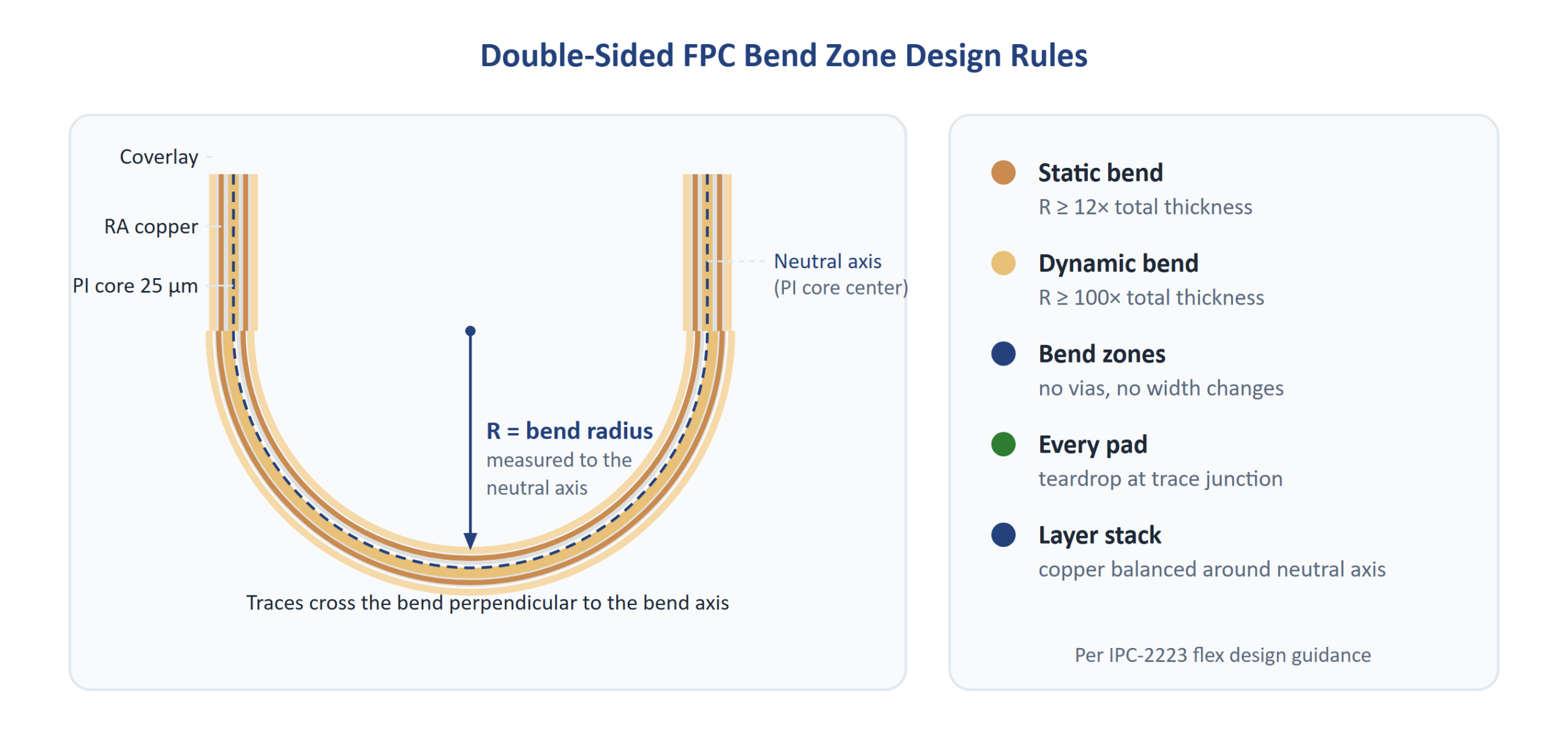
Via placement deserves special attention on a double-sided medical FPC. Place PTH vias outside active bend areas, support them with stiffeners where the layout allows, and anchor every pad-to-trace junction with a teardrop so thermal cycling and flex stress cannot lift the annular ring over time.
If your layout pushes against any of these limits, send the design anyway. Our DFM engineers review every medical FPC file individually and propose the smallest workable adjustment — a shifted trace, a relocated via, or a rebalanced stackup — so the board bends the way your product needs it to, before tooling begins.
Where a medical design stacks additional constraints — impedance-controlled traces for RF sensing, shield layers for biopotential signals, or extreme thickness budgets for catheter-scale assemblies — bring those targets into the first conversation. Defining them early lets our engineers propose a stackup that meets every constraint at once, instead of discovering conflicts after layout is frozen.
File Preparation, Panelization and Stiffeners
Clean input files keep a flex build on schedule. We accept Gerber (RS-274X), ODB++, and IPC-2581 with Excellon drill files, plus a stackup drawing that states PI thickness, copper weights, adhesive layers, coverlay openings, and stiffener locations. Marking bend zones and their minimum radii directly on the drawing removes the most common source of back-and-forth engineering questions.
For production, the standard working panel is 60x40mm, with 300x250mm available for volume programs. Panel rails, breakaway tabs, and fiducials are planned around your array, so a design that validates at prototype scale runs unchanged at volume — no requalification is needed between first article and mass production.
Documentation travels with every batch: certificates of conformance for polyimide, copper, adhesive, and coverlay lots, plus the inspection summary and test records. That packet gives your assembly partner and quality team full traceability from laminate lot to shipped circuit, ready to file with your own quality system.
Stiffener drawings deserve the same care as the circuit itself. Supply stiffener locations as a separate mechanical layer in your Gerber set, note the material and thickness for each region, and flag any connector pads that need precise placement tolerances. Our CAM team reviews the stiffener layer against your component placement and panel rails during DFM, catching clearance conflicts before they cost a production run.
Scaling From Prototype to Volume Production
Medical programs rarely stay at prototype scale for long. A design that starts as a handful of sensor patches for clinical evaluation needs to ramp into thousands of units without a requalification cycle in between. Our double-sided FPC platform is built for exactly that path: the same stackup, the same coverlay openings, and the same stiffener layout carry from first article to full production.
Because the build runs on dedicated flex lines with batch-recorded process parameters, the boards you approve at prototype stage are the boards your contract manufacturer receives at volume. Engineering change orders are handled with revision-controlled documentation, so every revision of your medical FPC is traceable to its build records.
When volumes grow further, the same build scales onto 998PCB Group capacity, keeping material sourcing and process discipline consistent across facilities. You keep one engineering point of contact while capacity flexes with your program — from early clinical builds to full market launch.
Planning that ramp starts with the quote. Share your expected volumes, target launch dates, and any regulatory documentation your program requires, and our team will map the build plan against them — DFM review, prototype build, first-article approval, and volume release as connected milestones rather than disconnected orders. The same engineering team follows your program across all four stages, so nothing is re-explained at each handoff.
Our Quality Guarantee for Medical FPCs
Medical device electronics demand the highest levels of quality and traceability. We implement rigorous testing protocols on every board:
- 100% AOI Inspection: Automated Optical Inspection scans every FPC for trace breaks, shorts, and coverlay alignment errors.
- 100% Electrical Testing (E-Test): Flying probe or fixture-based testing verifies continuity and isolation.
- Flex Cycle Testing: Available dynamic flex testing per IPC-TM-650 to verify flex fatigue life.
- Material Traceability: Full material lot traceability with certificates of conformance for medical device documentation.
- Certifications: ISO 9001:2015, ISO 14001, UL (E305905), RoHS compliant. IPC Class 3 capability available on request for critical applications.
Why Choose Season PCB for Your Medical FPC?
With nearly 20 years of experience in PCB manufacturing, Season Multilayer Circuit has served over 8,000 global clients in medical devices, wearable electronics, and consumer electronics. Our three manufacturing facilities provide capacity for both rapid prototyping and high-volume production.
We understand that medical device electronics demand biocompatibility, reliability, and full traceability. That is why every double-sided medical FPC we ship is backed by:
- Free DFM file checking before production
- 24/7 dedicated engineering support
- Schedule discipline — every build is planned around your project timelines
- Prototype-to-production flexibility at every project stage
- Engineering fee waivers on bulk production orders
Season PCB specializes in double-sided medical FPC manufacturing for wearable and implantable-grade medical device applications. Our medical FPC products feature medical-grade polyimide substrates, dynamic flex capability, and precision sensor integration. Each medical FPC is built to IPC manufacturing standards with documented material traceability.
For your medical FPC needs, Season PCB provides fast turnaround, competitive pricing, and ISO-certified quality. Contact us for medical FPC manufacturing today.
Our medical FPC boards comply with UL safety certifications and IPC manufacturing standards. Each medical FPC undergoes flex cycle testing, and material documentation is retained for every production batch. The same build scales to high volumes on 998PCB Group’s FPC and rigid-flex PCB lines at the group’s Shenzhen campus.
Frequently Asked Questions
Are your medical FPCs biocompatible?
Yes, we use medical-grade polyimide substrates and adhesives available with suppliers’ ISO 10993 test data (cytotoxicity, irritation, sensitization). For implantable-grade applications, USP Class VI certified material options are available. Material test data sheets are available upon request.
What flex cycle life can your FPCs achieve?
For dynamic flex applications, our FPCs are tested to 100,000+ flex cycles at the specified bend radius. The actual flex life depends on copper type (rolled-annealed vs. electrodeposited), trace routing, bend radius, and FPC thickness. We provide flex life estimation based on your specific design parameters.
Can you provide material traceability for medical device documentation?
Yes, we provide full material lot traceability with certificates of conformance (CoC) for all materials used. This includes polyimide substrate, copper foil, adhesive, coverlay, and surface finish materials. Documentation packages (material data sheets, CoCs, and lot traceability records) are provided to support your own regulatory submission process.
What engineering support is included with every medical FPC order?
You can start with a single prototype and scale smoothly into volume production. Every order includes free DFM file checking before production, so our engineers review your design for manufacturability, plus 24/7 dedicated engineering support. Engineering fees are waived on bulk production orders, and delivery milestones are confirmed in writing before each build starts.
Which materials and surface finishes can you use for medical FPCs?
Our standard base material is polyimide at 25 µm, available from 12.5 µm to 75 µm, with PET as a lower-cost option; coverlay is PI 12.5/25/50 µm or solder mask. Copper ranges from 1/3 oz (12 µm) to 2 oz (70 µm) depending on current-carrying requirements. ENIG is our standard surface finish, with OSP, immersion silver, and tin available to suit your assembly process. For implantable-grade applications we supply USP Class VI certified material options with suppliers’ ISO 10993 test data.
Ready to start your Medical FPC project?
From first prototype to full production ramp, our engineering team is ready to support your medical FPC project with DFM review, flex life analysis, and fast-turn fabrication.
Tel: (+86) 18681528532 | WhatsApp: +86 18681528532
E-mail: roc@season-pcb.com