Book Appointment Now

6-Layer Rigid-Flex PCB
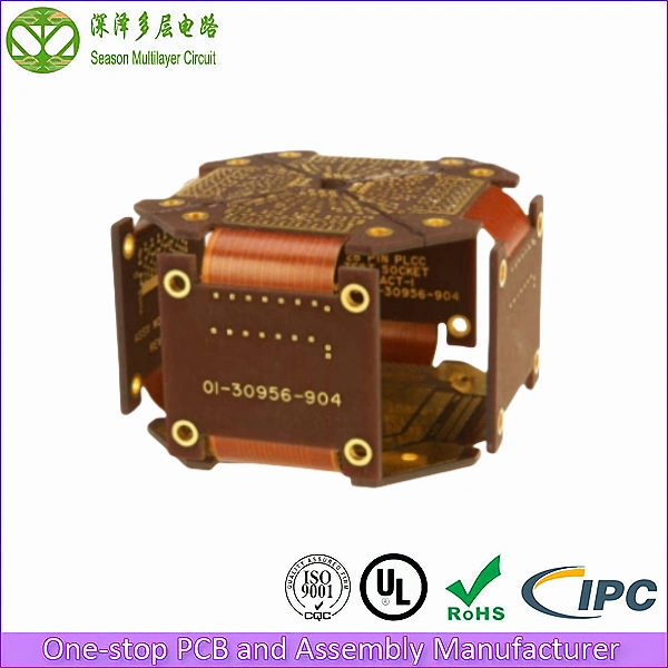
Advanced rigid-flex PCBs combining 6-layer rigid sections with multi-layer flexible zones for aerospace, medical, and consumer electronics applications requiring 3D packaging, weight reduction, and reliable dynamic interconnects.
Rigid-flex PCBs eliminate bulky connectors and cable assemblies by integrating flexible circuits directly into rigid board sections, enabling 3D packaging, weight reduction, and improved reliability. At Season Multilayer Circuit, we manufacture 6-layer rigid-flex PCBs with precise layer registration, reliable flex-to-rigid transitions, and aerospace-grade reliability for the most demanding applications.
6
Layer Count
4/4 mil
Min. Trace/Space
0.15 mm
Min. Via Diameter
Tg 180
Glass Transition Temp
1–2 µ”
ENIG Gold Thickness
ISO 9001:2015
ISO 14001
UL (E305905)
IPC Class 2 / Class 3
RoHS
6-Layer Rigid-Flex PCB Stackup Diagram
Our 6-layer rigid-flex stackup combines FR-4 rigid sections with polyimide flexible zones, with copper layers continuing seamlessly through the transition area. This architecture eliminates connectors, reduces weight, and enables complex 3D folding for compact electronic assemblies.
- Rigid Top Layer (Copper/Plated): Component placement on rigid FR-4 section
- Flex Layer 1 (Ground): Ground plane continuing through flex zone as flex layer
- Flex Layer 2 (Signal): Polyimide-based flexible signal routing in flex zone
- Flex Layer 3 (Signal): Polyimide-based flexible signal routing in flex zone
- Flex Layer 4 (Power): Power plane continuing through flex zone as flex layer
- Rigid Bot Layer (Copper/Plated): Bottom routing on rigid FR-4 section
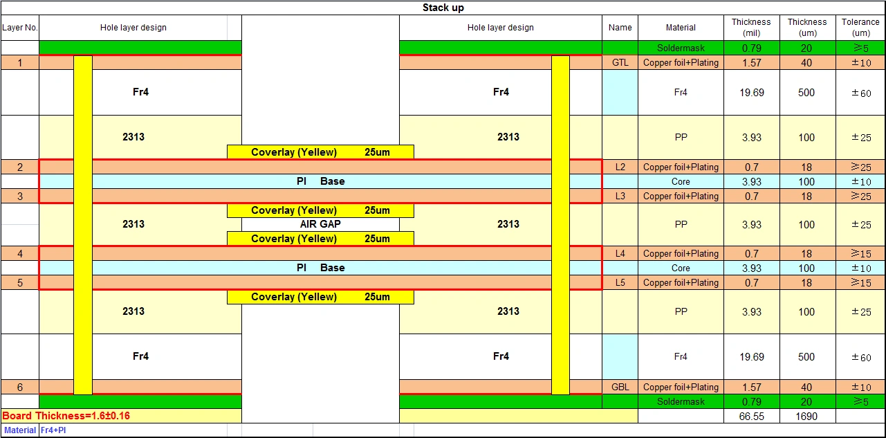
In the rigid sections, all 6 layers are present with FR-4 substrate. In the flex zones, only the flexible polyimide layers (L3, L4) and selected power/ground layers (L2, L5) continue, while rigid-only layers (L1, L6) terminate at the rigid-flex boundary. This selective layer continuation is critical for maintaining flex flexibility while preserving signal integrity.
Technical Capability & Specifications
| Parameter | Specification | Advanced Capabilities |
|---|---|---|
| Layer Count | 6 Layer Rigid-Flex | 2-10L (Mass); 2-12L (Sample) |
| Rigid Material | FR-4 S1000-2M (Tg 180) + PI | SY, NY, TUC, ZY, EMC, KB, ITEQ, Rogers |
| Flex Material | Polyimide (PI) 25 µm | PI 12.5/25/50/75 µm |
| Board Thickness | Rigid: 1.2mm / Flex: 0.15mm | Rigid: 0.2-3.2mm / Flex: 0.05-0.30mm |
| Panel Size | 120x80mm/1 | 400x300mm (Mass) |
| Copper Thickness | Outer: 1 oz Inner: 0.5 oz | Outer: 1/3–12 oz Inner: 1/4–12 oz |
| Min Drill Size | 0.15mm | 0.127mm (Sample) |
| Min Trace Width/Spacing | 4/4 mil | 3/3 mil (Sample) |
| Flex Bend Radius | 10x thickness | 6x thickness (Dynamic) |
| Surface Finish | ENIG | ENIG, ENEPIG, OSP, Immersion Silver |
| Solder Mask | Green (Rigid) | Green, Black, Blue, Red, White, Purple |
| Flex Cycle Life | 100K+ cycles | 500K+ cycles (Dynamic RA copper) |
Key Advantages of Our Rigid-Flex PCB
- Connector Elimination: Rigid-flex integration eliminates bulky board-to-board connectors and ribbon cables, reducing assembly weight by up to 75% and eliminating connector failure points.
- 3D Packaging Capability: Flexible zones enable folding and bending to fit complex mechanical enclosures, achieving 60% volume reduction compared to rigid board assemblies.
- Enhanced Reliability: No connectors means no contact oxidation, no insertion wear, and no misalignment issues. The continuous copper trace from rigid to flex provides superior signal integrity and mechanical reliability.
- Selective Layer Continuation: Only required signal and power layers continue through the flex zone, maintaining maximum flexibility while preserving signal integrity in rigid sections.
- Aerospace-Grade Construction: High-TG FR4 (Tg 180) rigid sections with polyimide flex zones meet the demanding thermal and mechanical requirements of aerospace and defense applications.
Overcoming Critical Challenges in Rigid-Flex Design
When sourcing rigid-flex PCBs, engineers encounter three critical challenges. Here is how our engineering team eliminates them:
1. Rigid-to-Flex Transition Reliability
The Problem: The boundary between rigid and flex sections is the most stress-prone area of a rigid-flex PCB. Poor transition design causes copper trace cracks and delamination at the rigid-flex interface after thermal cycling or mechanical stress.
Our Solution: We follow IPC-2223 rigid-flex design guidelines with optimized transition windows. The rigid sections use no-flow prepreg at the flex boundary to prevent adhesive flow into the flex zone. We also add tie-down tabs and gradual trace tapering at transitions to distribute stress and prevent crack propagation.
2. Layer Registration Across Rigid-Flex Boundary
The Problem: Rigid-flex PCBs require precise alignment between rigid FR-4 layers and flexible polyimide layers. Misalignment causes via drilling errors, layer shorts, and signal discontinuity at the transition zone.
Our Solution: Our manufacturing process uses precision pinning and optical alignment systems to maintain layer registration within +/-0.05mm across the rigid-flex boundary. Pre-lamination alignment verification and post-lamination X-ray inspection ensure registration integrity before drilling.
3. Flex Zone Design for Dynamic Applications
The Problem: Flexible zones that undergo repeated bending (e.g., folding display hinges) require specialized design. Incorrect trace routing, copper type, or bend radius causes rapid flex fatigue failure.
Our Solution: For dynamic flex zones, we use rolled-annealed (RA) copper with hatched polygon ground planes and perpendicular-to-bend trace routing per IPC-2223. We specify minimum bend radius of 10x the flex thickness for dynamic applications (6x for static). Our designs are verified to 100K+ flex cycles.
Where Our Rigid-Flex PCBs Are Used
Our 6-layer rigid-flex PCBs are deployed across a wide range of high-reliability applications:
- Aerospace Avionics: Satellite and aircraft electronics requiring weight reduction, 3D packaging, and zero-connector reliability in vibration and G-force environments.
- Medical Devices: Endoscope camera modules, hearing aids, and wearable health monitors requiring compact, foldable, and biocompatible rigid-flex assemblies.
- Consumer Electronics: Folding smartphones, wearable devices, and compact cameras requiring dynamic flex hinges and 3D space optimization.
- Military and Defense: Ruggedized communication devices and weapon systems requiring extreme reliability and environmental resistance.
- Industrial Robotics: Robot arm joint electronics and automated inspection systems requiring dynamic flex for continuous movement.
Our Quality Guarantee for Rigid-Flex PCBs
Rigid-flex PCBs are used in critical applications where failure is not an option. We implement rigorous testing protocols on every board:
- 100% AOI Inspection: Automated Optical Inspection scans every layer for trace breaks, shorts, and registration errors.
- 100% Electrical Testing (E-Test): Flying probe or fixture-based testing verifies continuity across rigid-flex boundaries.
- X-Ray Inspection: X-ray verification of layer registration at rigid-flex transitions.
- Flex Cycle Testing: Available dynamic flex testing to verify flex zone reliability under repeated bending.
- Certifications: ISO 9001:2015, ISO 14001, UL (E305905), RoHS compliant. IPC Class 3 available for aerospace and defense.
Why Choose Season PCB for Your Rigid-Flex PCB?
With nearly 20 years of experience in PCB manufacturing, Season Multilayer Circuit has served over 8,000 global clients in aerospace, medical devices, consumer electronics, and defense. Our three manufacturing facilities provide capacity for both rapid prototyping and high-volume production.
We understand that rigid-flex PCBs are used in critical applications where reliability is paramount. That is why every 6-layer rigid-flex PCB we ship is backed by:
- Free DFM file checking before production — including rigid-flex transition zone review
- 24/7 dedicated engineering support — including rigid-flex design consultation
- Guaranteed on-time delivery
- No minimum order quantity — from 1 prototype to 50,000+ units
- Engineering fee waivers on bulk production orders
Season PCB specializes in 6-layer rigid-flex PCB manufacturing for aerospace, medical, and consumer electronics applications. Our rigid-flex PCB products feature connector-free integration, 3D packaging capability, and aerospace-grade reliability. Each rigid-flex PCB meets IPC-2223 standards.
For your rigid-flex PCB needs, Season PCB provides fast turnaround, competitive pricing, and ISO-certified quality. Contact us for rigid-flex PCB manufacturing today.
Our rigid-flex PCB boards comply with UL safety certifications and IPC manufacturing standards. Each rigid-flex PCB undergoes transition zone inspection and flex cycle testing. Volume programmes of this build run on 998PCB Group’s FPC and rigid-flex PCB lines under the same quality system.
Frequently Asked Questions
What is the difference between rigid-flex and flexible PCB?
A flexible PCB (FPC) is entirely flexible with polyimide substrate throughout. A rigid-flex PCB combines rigid FR-4 sections with flexible polyimide zones in a single board. The rigid sections hold components while the flex zones enable 3D folding and interconnection between rigid sections without connectors.
What bend radius do you recommend for rigid-flex PCBs?
For static applications (one-time bend during assembly), minimum bend radius is 6x the flex thickness. For dynamic applications (repeated bending), we recommend 10x the flex thickness. These guidelines per IPC-2223 ensure long-term flex reliability without copper fatigue.
What is the lead time for rigid-flex PCB prototypes?
Rigid-flex PCBs require specialized manufacturing processes including selective layer lamination and precision alignment. Standard prototype lead time is 12-15 working days. Expedited 8-day service is available. Mass production typically takes 20-25 working days.
What materials and surface finishes do you use for 6-layer rigid-flex PCBs?
Rigid sections use FR-4 S1000-2M (Tg 180), with SY, NY, TUC, ZY, EMC, KB, ITEQ, and Rogers laminates available on request. Flexible zones use 25 µm polyimide, with 12.5, 50, and 75 µm optional. Copper is 1 oz on outer layers and 0.5 oz on inner layers. ENIG is our standard surface finish, with ENEPIG, OSP, and immersion silver available. Solder mask is green on rigid sections, with black, blue, red, white, and purple optional.
How do you verify quality on rigid-flex boards?
Every board passes 100% AOI with per-layer short, open, and registration checks, plus 100% electrical testing by flying probe or fixture, including continuity across the rigid-flex boundary. X-Ray inspection verifies layer alignment in the transition zones, and flex cycle testing validates 100,000+ bend cycles (500,000+ with RA copper). Layer-to-layer registration is held to +/-0.05mm. We are certified to ISO 9001:2015, ISO 14001, UL (E305905), and RoHS, and build to IPC Class 3 for aerospace and defense applications.
Ready to start your Rigid-Flex PCB project?
Whether you need 5 pieces for prototyping or 50,000 for mass production, our engineering team is ready to support your rigid-flex project with DFM review, flex zone analysis, and fast-turn fabrication.
Tel: (+86) 18681528532 (WhatsApp)
E-mail: roc@season-pcb.com