Book Appointment Now

A practical guide to PCB laminate selection: how FR4, high-temperature, halogen-free and low-loss materials differ in Tg, Dk, Df, cost and applications.
PCB Laminate Selection Guide: From Standard FR4 to Low-Loss Materials
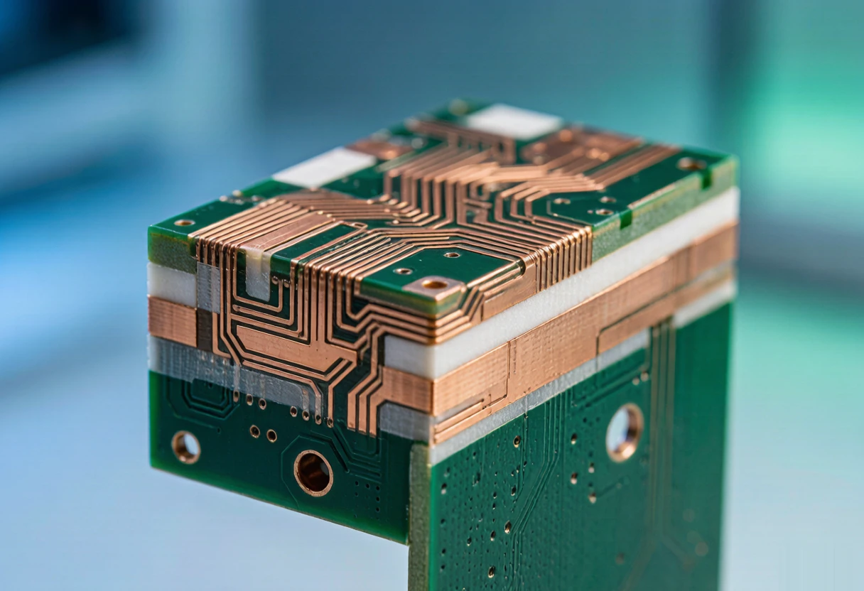
Every electrical property a board has starts in its base material, and yet PCB laminate selection is routinely postponed until layout is finished, when the stackup is already constrained. The confusion is understandable: glass-epoxy, elevated-Tg, halogen-free and low-loss grades have similar names, overlapping specifications and cost levels that differ by several times. Choose above the requirement and the budget absorbs it across every square meter produced; choose below it and the reliability risk appears where it is most expensive to fix.
This guide works through the four material classes buyers actually choose between, built on the five parameters that describe any laminate, and closes with a five-step selection method, two comparison tables and the four mistakes that cost the most. The goal is a decision that can be defended to both the design team and the finance team.
Table of Contents
- What a PCB Laminate Is Made Of
- FR4: The Default Choice and Where It Runs Out
- When Heat Demands More: Grades Above Tg 170 °C
- Halogen-Free Laminates: Compliance Defined by Numbers
- Low-Loss Materials for High-Speed Signals
- Hybrid Stackups: Pay for Low Loss Only Where Signals Run
- A Five-Step PCB Laminate Selection Method
- Laminate Comparison: Four Classes Side by Side
- Which Material for Which Application
- Four Selection Mistakes That Cost More Than They Save
- Frequently Asked Questions About PCB Laminate Selection
- Get the Material Reviewed Before the Stackup Is Frozen
What a PCB Laminate Is Made Of
Every rigid board starts as the same sandwich: woven glass cloth for mechanical strength, resin to bind it and define the electrical behavior, and copper foil to carry the circuits. What distinguishes one grade from another is almost always the resin system. Epoxy dominates the conventional classes; modified epoxies, hydrocarbon resins and PTFE take over as signal speeds rise.
Five parameters do most of the describing, and knowing them turns any datasheet into a readable document:
- Tg, the glass transition temperature. The point where the rigid, glassy resin turns soft and rubbery. Above it, mechanical strength, insulation and dimensional stability all degrade, so Tg sets the practical thermal ceiling for handling and assembly.
- Td, the decomposition temperature. Where the resin begins to chemically break down and lose weight. Higher Td means more margin against thermal aging, not just against a single reflow cycle.
- Dk, the dielectric constant. It sets trace impedance and signal velocity. High-frequency designs need it stable and uniform across the panel, not merely low.
- Df, the dissipation factor. The share of signal energy the material converts to heat. This single number decides how far a Gbps-class signal can travel before the eye diagram closes.
- Moisture absorption and CTE. Water uptake shifts Dk and threatens reliability in humid environments; the coefficient of thermal expansion, especially in the Z axis, decides how plated vias survive repeated heating cycles.
FR4: The Default Choice and Where It Runs Out
FR4 is the workhorse grade: woven glass cloth in an epoxy resin system with a UL 94 V-0 flame rating, covering consumer electronics, power supplies, home appliances and most industrial control. Its specification envelope is well known: glass transition around 130 to 140 °C, Dk of roughly 4.2 to 4.8 at 1 GHz, dissipation factor of 0.015 to 0.020, decomposition temperature near 310 to 340 °C. Supply is deep, processing is mature, and the overwhelming majority of boards from 2 to 30 layers run on it economically.
Two limits define where it stops being the right answer. The first is thermal: with a glass transition near 130 to 140 °C, conventional grades have limited headroom against lead-free assembly, whose reflow peaks reach 245 to 260 °C, and against sustained high operating temperatures. The second is loss: a dissipation factor around 0.015 to 0.020 visibly degrades signals once data rates push past roughly 10 Gbps, which rules conventional grades out of high-speed serial links and RF front ends.
For conventional consumer, power and industrial products neither limit is ever reached, and FR4 remains the correct answer, not the cheap compromise. Reference builds in this class include our 4-layer automotive board and the wider ranges documented in our PCB materials and laminates guide.
When Heat Demands More: Grades Above Tg 170 °C
Lead-free assembly is what created the demand for elevated glass-transition temperatures. SAC305 solder melts near 217 °C, roughly 34 °C above the tin-lead alloys it replaced, so reflow profiles now peak at 245 to 260 °C. A conventional resin system pushed through that repeatedly can soften, delaminate or blister, and the Z-axis expansion that comes with it strains plated via barrels from the inside.
Grades specified at Tg 170, 175 or 180 °C hold their mechanical and electrical properties through those profiles. These high-Tg systems expand less along the Z axis, which is what protects via reliability in thick, high-layer-count boards, and they retain dimensional stability in hot operating environments such as engine compartments, power modules and server chassis.
The premium is moderate: typically 20% to 40% over conventional grades, far below the low-loss class. The selection cue is thermal, not electrical. If the product goes through lead-free reflow, lives in a hot environment, or carries a long-warranty reliability requirement, an elevated-Tg grade is the justified default; if none of those apply, it is budget spent on headroom the design will never use.
Halogen-Free Laminates: Compliance Defined by Numbers
Conventional flame retardance relies on brominated epoxy chemistry, which can release corrosive and toxic compounds when burned. Halogen-free grades replace it with phosphorus- and nitrogen-based systems while still meeting the V-0 flame rating under the UL 94 standard. The regulatory definition is numeric, set out in the IPC-4101 specification family: chlorine below 900 ppm, bromine below 900 ppm, and total halogens below 1,500 ppm. A material either meets those numbers or is not halogen-free, whatever the marketing sheet says.
The cost premium is modest, typically 5% to 15% over conventional grades, and it keeps narrowing as volumes grow. Reliability is not the trade-off people expect it to be: thermal stability and lead-free compatibility are on par with the classes above, and the real differences live in cost and processing window rather than in performance.
Halogen-free and elevated-Tg are independent axes, and many grades carry both properties at once. A typical example on our line is S1150G, a halogen-free grade specified at Tg 150 °C and above, which covers export products that need environmental compliance and lead-free assembly in the same build. For products shipping into the EU or to customers with explicit halogen-free sourcing policies, specifying the class directly is simpler than retrofitting it later.
Low-Loss Materials for High-Speed Signals
Once serial links run at Gbps rates, the dissipation factor of the dielectric becomes the design constraint. Conventional glass-epoxy at 0.015 to 0.020 Df attenuates 10 Gbps-class signals to the point where the eye closes and the bit error rate climbs. Low-loss systems attack the number directly, reaching 0.002 to 0.010 while holding Dk uniform enough for tight impedance control.
Three resin families cover the range. Modified epoxy systems sit at Df 0.008 to 0.012 and serve as the economical entry point between conventional grades and the specialty class. PPO and hydrocarbon systems reach Df 0.003 to 0.008 and carry the 25 to 56 Gbps digital links found in servers, switches and optical modules. PTFE systems go furthest, down to Df 0.002 with Dk as low as 2.2, and own the RF, microwave and antenna applications where every tenth of Dk tolerance matters.
The premium is the steepest of the four classes, several times the conventional baseline, which is exactly why the material decision should follow the data rate rather than precede it. Builds in this class on our line include a double-sided high-frequency board and a 6-layer optical module board, both supplied with impedance test reports as standard.
Hybrid Stackups: Pay for Low Loss Only Where Signals Run
Not every layer of a high-speed board needs specialty material. Hybrid construction presses low-loss material only on the layers that carry critical signals and fills the rest of the stack with conventional or elevated-Tg layers, all bonded in a single lamination cycle. The electrical result is nearly identical where it matters; the material cost lands only on the layers that earn it.
Hybrids are standard practice in servers, switches and optical modules, and the engineering work sits in managing the mismatch: different resin systems expand and cure differently, so the press cycle and the registration plan have to be built around the combination. A fab that runs hybrids routinely treats this as normal production; one that does not will quote it cautiously or not at all, which is worth knowing before the stackup is frozen.
The selection pattern to remember: a 14-layer board with four high-speed signal layers usually does not need fourteen layers of low-loss material. Asking for a hybrid evaluation at quotation stage is the single highest-yield question in this entire guide, and it is the reason our 12-layer HDI core board class of builds reviews material assignment layer by layer rather than in bulk.
A Five-Step PCB Laminate Selection Method
Material choice compresses into a repeatable sequence once the classes are understood. Run the five steps in order and the answer usually makes itself:
- Pin the signal speed. Links above roughly 10 Gbps go straight to the low-loss class; below that, conventional and elevated-Tg grades remain in play. This step eliminates half the menu immediately.
- Assess the thermal environment. Lead-free assembly, high ambient temperature or strict long-term reliability push the choice to grades with glass transition at or above 170 °C.
- Check the compliance requirements. EU export, corporate environmental policy or a customer mandate selects the halogen-free axis, which can be combined with either thermal class.
- Cost the whole picture. Material price, processing yield and field-failure risk belong in one column. A slightly dearer grade that protects yield is cheaper than the cheapest one that does not.
- Validate on prototypes. Confirm impedance, thermal performance and reliability on sample builds before the volume order locks the stackup, and before the choice is baked into every unit thereafter.
The order matters. Deciding on cost before speed and temperature produces a figure that later gets revised at higher expense; deciding on material before compliance produces boards that fail inbound inspection at the customer. The five steps are cheap in this direction and expensive in the other.
Laminate Comparison: Four Classes Side by Side
The table below compresses the four classes into the parameters that drive the decision. Values are typical specification ranges at 1 GHz for the dielectric figures; individual grades vary, and the datasheet of the assigned grade always governs.
| Parameter | FR4 (conventional) | Elevated-Tg grade | Halogen-free grade | Low-loss high-speed |
|---|---|---|---|---|
| Glass transition (Tg) | 130 to 140 °C | 170 to 180 °C | 130 to 160 °C | Depends on resin system, some above 180 °C |
| Dk at 1 GHz | 4.2 to 4.8 | 4.2 to 4.7 | 4.0 to 4.7 | 3.0 to 4.5 (PTFE down to 2.2) |
| Df at 1 GHz | 0.015 to 0.020 | 0.015 to 0.020 | 0.013 to 0.018 | 0.002 to 0.010 |
| Thermal class | Conventional | High, lead-free friendly | Mid to high | High, resin-system dependent |
| Relative cost | Baseline | About 1.2 to 1.4 | About 1.05 to 1.15 | 2 to 5 and above |
| Typical applications | Consumer, power, appliances, industrial control | Automotive, servers, power modules | Laptops, phones, wearables, base stations | 5G, switches, optical modules, radar |
| First-choice scenario | Best value for conventional builds | Lead-free assembly and hot environments | Environmental compliance and export products | High-speed links and RF front ends |
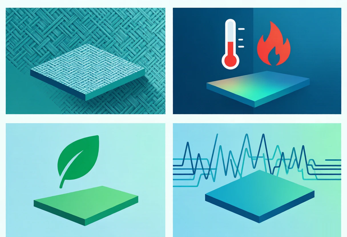
One reading rule keeps this table honest: the cost column is relative, not absolute, and it interacts with the other columns. A halogen-free grade already carries a premium; adding an elevated glass transition on top produces a combined class whose multiplier sits between the two, not below either. That is exactly the kind of detail a stackup review settles before quotation rather than after.
Which Material for Which Application
For teams that need an answer faster than a five-step method, the scenario table below is the shortcut. The middle column names the material class; the right column names the caution that comes with it.
| Application | Recommended material class | Key caution |
|---|---|---|
| Consumer electronics, appliances, power, industrial control | FR4, conventional Tg | Best supply and value; no upgrade needed |
| Automotive electronics, lead-free assembly, hot environments | Elevated-Tg grade, 170 °C and above | Check resistance to CAF and delamination under humidity |
| Laptops, phones, wearables for export | Halogen-free grade | Confirm V-0 rating and request the halogen test report |
| 5G base stations, switches, optical modules | Low-loss grade, mid class | Check Dk and Df consistency; request impedance test reports |
| RF, microwave, antenna arrays | PTFE or ceramic-filled systems | Watch Dk tolerance; assembly window differs from epoxy |
| High-layer-count server and storage boards | Hybrid: low-loss on signal layers only | Requires a fab with routine hybrid lamination experience |
| Prototype and validation stage | Conventional FR4 first | Verify the design on the economical grade, then switch for volume |
The last row is the one most often skipped. Prototyping the design on conventional material and upgrading the stackup for volume protects the budget during the iterations where boards get scrapped anyway, and it isolates any prototype failure to the design rather than to an unfamiliar specialty process.
Four Selection Mistakes That Cost More Than They Save
- Assuming the dearest material is the safest choice. A low-loss grade on a board whose fastest link runs at 480 Mbps buys nothing. Material class should follow the requirement, and the requirement is measurable.
- Assuming halogen-free means weaker. Flame rating and electrical performance are on par with brominated chemistry; the honest trade-offs are cost and processing window, not reliability.
- Treating thermal grade and signal grade as interchangeable. A high glass transition solves heat; a low dissipation factor solves loss. One never substitutes for the other, and boards need the right one on the right axis.
- Costing material price alone. The grade that saves a few percent on laminate but lowers first-pass yield, or that fails a customer audit two years later, was never the cheaper option. Total cost includes yield and field risk.
Frequently Asked Questions About PCB Laminate Selection
What parameters matter most in PCB laminate selection?
Five numbers do most of the work: Tg for the thermal ceiling, Td for long-term thermal aging, Dk for impedance and velocity, Df for signal loss at speed, and moisture absorption together with CTE for dimensional stability and via reliability. For a high-speed design, Df and Dk uniformity dominate; for an automotive or power application, Tg and CTE dominate. Match the parameter that carries the project’s risk, then compare grades on cost.
How do grades above Tg 170 °C differ from standard FR4?
The glass transition rises from roughly 130 to 140 °C to 170 °C or more, so the material stays rigid and dimensionally stable through lead-free reflow peaks of 245 to 260 °C. Z-axis expansion is lower, which protects plated vias in thick boards, and the grades hold their properties in sustained hot environments. The premium is typically 20% to 40% over conventional material.
Are halogen-free materials less reliable?
No. Modern halogen-free grades meet the same UL 94 V-0 flame rating, handle lead-free assembly and deliver electrical performance comparable to brominated chemistry. The genuine differences are a modest cost premium, typically 5% to 15%, and a somewhat narrower processing window at the fab. For export products, compliance value usually outweighs both.
Can different materials be combined in one stackup?
Yes, and this is standard practice for high-speed products. Hybrid construction presses low-loss material on the signal-critical layers and conventional or elevated-Tg material elsewhere in a single lamination cycle. The electrical performance where it matters is preserved while the material premium applies only to the layers that need it. The fab must manage cure and expansion mismatch between systems, so hybrid experience is worth confirming at quotation.
When is a low-loss material actually necessary?
When data rates make dissipation factor the binding constraint. Conventional glass-epoxy at Df 0.015 to 0.020 starts visibly degrading signals above roughly 10 Gbps. Modified epoxies serve mid-range needs, PPO and hydrocarbon systems carry 25 to 56 Gbps links, and PTFE systems down to Df 0.002 serve RF, microwave and antenna work. Below the Gbps threshold, the low-loss premium usually buys nothing measurable.
How much more does an elevated-Tg material cost than conventional FR4?
Typically 20% to 40% above the conventional baseline, depending on the grade and the lamination assignment. That places it well below the low-loss class, where multipliers of two to five times are normal. Because the premium is moderate, the decision should rest on whether the thermal requirement exists at all, not on the cost difference itself.
Should I prototype on FR4 before committing to a specialty material?
In most cases yes. Prototyping on conventional material validates the design at the lowest cost per iteration and keeps early failures attributable to the design rather than to a specialty process. Once the layout is proven, move the validated stackup to the material class the requirements demand, and re-check impedance on the first production panels, because the dielectric change shifts the controlled-impedance geometry.
Get the Material Reviewed Before the Stackup Is Frozen
Send the design with layer count, target data rates, assembly process, environmental requirements and any compliance mandate. The engineering team returns a material recommendation with the stackup, the relative cost position of each candidate grade and, where a hybrid build is possible, the savings of assigning low-loss material only to the layers that need it.
The review is part of our PCB manufacturing service, and it is the cheapest point in the project to discover that a class upgrade was unnecessary, or that the intended one would have missed a thermal requirement.