Book Appointment Now

What an energy storage PCB really demands: heavy copper capability, wide-temperature laminates, creepage discipline and a supplier audit you can run in one call.
Energy Storage PCB: Heavy Copper, Materials and Supplier Audit
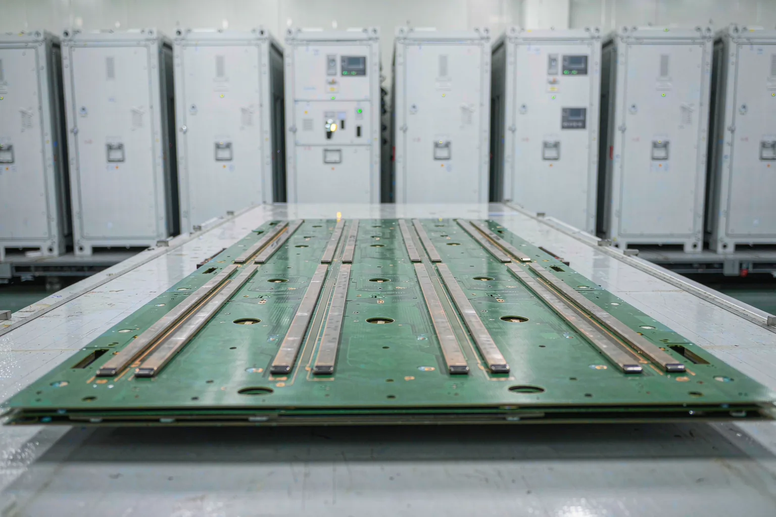
Battery cabinets, PCS units and rack-mounted storage systems push power electronics into a regime where ordinary board specifications stop being good enough. High bus currents, wide outdoor temperature swings and multi-year duty cycles turn small laminate and copper decisions into field-failure risks — and most rejected quotes trace back to a requirement that was never written down. This guide sets out what an energy storage PCB actually demands, how to audit a supplier’s real capability, and what a complete RFQ looks like.
Everything below is written from the manufacturing side of the conversation. The capability bands quoted are the ones our engineering team works with daily — 2–30 layers in production, copper weights up to 6 oz per layer in mass production and 12 oz on sample builds — so the checklist doubles as the same review our engineers run when a storage stackup lands on their desk. Where a figure depends on the specific design, it is flagged for per-order engineering review rather than promised blindly.
Table of Contents
- What Is an Energy Storage PCB and Why Is It Harder Than a Standard Build
- Four Requirements That Define an Energy Storage PCB
- Heavy Copper: The Capability That Separates Storage Board Suppliers
- Laminate Choices for Wide-Temperature, Long-Life Operation
- Creepage, Clearance and Flammability in Battery Cabinets
- How to Audit an Energy Storage PCB Supplier: Five Dimensions
- Typical Energy Storage PCB Configuration for RFQs
- From RFQ to Small-Batch Validation: A Three-Step Path
- Three Review-Stage Details Buyers Often Miss
- FAQ
- Get Your Energy Storage PCB Stackup Reviewed
What Is an Energy Storage PCB and Why Is It Harder Than a Standard Build
An energy storage PCB is the board set inside a storage system that carries power conversion, battery management and cell-sampling functions: the main-control board, the sampling and balancing boards, and the driver stages around the DC-DC and inverter sections. Electrically it looks familiar — microcontrollers, communication interfaces, sense circuits — but the environment it lives in is not.
Storage cabinets pack dense power electronics into a small enclosure with limited airflow. Bus bars and sampling harnesses run tens of amps continuously, cabinets sit outdoors through winter-to-summer temperature swings, and the duty cycle is measured in years of daily charge and discharge cycles. A board that is perfectly adequate for a consumer product can fail in this environment purely from heat and ageing.
That is why experienced buyers treat storage boards as a distinct sourcing category rather than a variant of a generic industrial board. The differences concentrate in four areas — current carrying, temperature, service life and safety — and each maps to a specific manufacturing capability, as the next section shows.
Four Requirements That Define an Energy Storage PCB
Before comparing suppliers, put the requirements on paper. The four rows below cover the majority of storage-specific engineering conversations, and each one corresponds to a process capability you can verify in a supplier audit.
| Requirement | Why It Matters | Process That Answers It |
|---|---|---|
| High bus and sampling currents | Copper that is too thin shows measurable temperature rise and voltage drop on power paths | Heavy copper fabrication, 2 oz as the practical starting point |
| Wide operating temperature | Outdoor cabinets cycle from winter nights to summer peak loads | Elevated-Tg laminate grades, Tg 170 and above, reviewed per cabinet temperature profile |
| Long service life | Charge and discharge cycles run for years and field failure costs far exceed board cost | CAF-resistant material selection and reliability-focused design rules |
| Safety and flammability | Multiple boards sit close together inside one cabinet | Flame-retardant laminate grades such as UL 94 V-0 plus creepage and clearance discipline |
Of the four, heavy copper is the dividing line. If the current path does not have enough metal, temperature rise and voltage drop both exceed budget no matter how good the layout is. Whether a factory can build heavy copper reliably — and quote it honestly — is one of the fastest ways to separate storage-capable suppliers from general-purpose ones.
Heavy Copper: The Capability That Separates Storage Board Suppliers
Heavy copper means any layer carrying roughly 2 oz (about 70 µm) of copper or more. In our production range, copper weights run from one-third ounce up to 6 oz per layer in mass production, and up to 12 oz on sample builds after engineering review. The practical entry point for storage current paths is 2 oz; motor-drive and DC-DC stages commonly justify 3–4 oz; distribution planes that feed many high-current branches go 6 oz and beyond.
Cost scales with weight in a predictable way: a 2 oz layer is typically quoted roughly 20–40% above the equivalent 1 oz layer, with heavier weights reviewed per build. That premium buys more than current capacity. Thick planes act as in-plane heat spreaders, pull heat toward mounting hardware and thermal vias, and give plated holes more cross-section to tolerate vibration and daily temperature cycling.
The decision that matters most at quotation is which layers carry which weight. The most common storage builds mix 2–6 oz copper on power and ground layers with standard 1 oz signal layers, rather than making the whole board heavy. Our engineering team verifies the trace-and-via arithmetic against the allowed temperature rise for every flagged net before quoting — that review is where optimistic assumptions usually get corrected. For the full selection logic, see our heavy copper PCB design guide.
Laminate Choices for Wide-Temperature, Long-Life Operation
The baseline laminate for storage boards is a Tg 170 FR-4 grade such as S1170G; builds that need more thermal headroom move to Tg 180 grades like S1000-2M. The reason is not a single number on the datasheet. It is how the material behaves after thousands of thermal cycles between cabinet ambient temperatures and self-heating from the power stages.
Two material properties deserve explicit attention. The first is glass-transition behaviour: a board that spends its life cycling across a warm operating band needs a Tg comfortably above the worst-case combination of ambient and board-level heating, or the resin system fatigues faster than the cells do. The second is CAF (conductive anodic filament) resistance. Storage cabinets run continuously at elevated humidity and bias, which is exactly the condition where CAF growth turns adjacent vias into leakage paths years down the road.
When you shortlist materials, start from the cabinet’s real temperature profile rather than the marketing datasheet, and let the supplier’s engineering review confirm the grade. Our PCB materials and laminates guide covers the grade families we stock, and the laminate selection guide walks through matching resin systems to operating conditions.
Creepage, Clearance and Flammability in Battery Cabinets
Inside a storage cabinet, boards sit close to bus bars, connectors and other live surfaces, so safety spacing is a design input, not an afterthought. Creepage and clearance requirements flow down from the end system’s safety specification, which depends on working voltage, pollution degree and the insulation category of each net. The board fabricator’s job is to hold those spacings through etch and solder-mask registration — which is why they must be written into the fabrication drawing, not negotiated after the first article.
Flammability follows the same pattern: dense multi-board cabinets typically demand high flame-retardant performance, and UL 94 V-0 laminate grades are the usual answer. Surface material properties matter here too. Comparative Tracking Index (CTI) decides how a laminate resists tracking across the surface under humidity and contamination, and higher-CTI materials allow tighter spacing on the same voltage. If your cabinet design is spacing-constrained, our high-CTI PCB guide explains the rating ladder and when the upgrade pays off.
Material certification closes the loop. Laminate grades and their flammability ratings are certified by testing bodies such as UL Solutions, and the certified grade should be named in the purchase specification so incoming material can be verified against it batch by batch.
How to Audit an Energy Storage PCB Supplier: Five Dimensions
Storage board quotes vary widely, and the difference is almost always capability rather than price luck. Rather than reading brochure claims, ask the five questions below and ask for evidence for each. A supplier that answers all five with specifics is one you can hand a power stackup to.
| Audit Dimension | What to Verify |
|---|---|
| Layer and copper capability | Production range of 2–30 layers; heavy copper up to 6 oz in mass production and 12 oz on sample builds after review; photos or cross-sections of actual heavy-copper runs |
| Engineering review depth | Whether current per net, copper weight, creepage and clearance are confirmed order by order, not assumed from a template |
| Test and inspection | 100% electrical test (flying probe or fixture), AOI records, and final-inspection data that can be retrieved per batch |
| Schedule discipline | Standard build windows confirmed at engineering review, with compressed options assessed against the actual process stack rather than quoted reflexively |
| Batch consistency | First-article parameters identical to production parameters, with full material and process traceability per batch |
If you can visit the factory, three stops tell you the most: the lamination floor (ask how press parameters are logged), the electrical test area (fixture and flying-probe coverage), and the final inspection bench (sampling strictness and record retention). Documentation discipline correlates with batch consistency better than any single machine on the floor. For the generic version of this checklist, our multilayer PCB manufacturer selection guide walks the same five dimensions for non-power builds, and our manufacturing capability page lists the production figures behind each row above.

Typical Energy Storage PCB Configuration for RFQs
When you send a storage board out to quote, a reference configuration saves a round of emails. The bands below reflect common builds for main-control and sampling boards in cabinet-scale systems; power conversion stages are reviewed separately because their copper and thermal demands differ.
| Item | Common Configuration | Note |
|---|---|---|
| Layer count | 4–8 layers for main-control and sampling boards | Production capability spans 2–30 layers; bus and power sections reviewed per structure |
| Copper weight | 2 oz on current paths as the starting point, increased per current-carrying requirement | Up to 6 oz in mass production, 12 oz on sample builds after review |
| Laminate | Tg 170 FR-4 grade as the baseline | Reviewed against the cabinet temperature profile and safety requirements |
| Trace and space | 3/3 mil as the standard rule | Widen high-current paths first; finer rules reserved for dense logic |
| Surface finish | ENIG as the default | Connector and keying areas selected per mating method |
These bands are starting points for discussion, not commitments — every figure is confirmed at engineering review against the actual net list. Storage control electronics increasingly carry fast communication signals, so controlled-impedance nets are common; they are typically quoted as an add-on of roughly 10–25% depending on how many nets the design controls, and the stackup should be reviewed before layout freezes. Boards in this class share a great deal with industrial builds — see, for example, our 10-layer HDI industrial control PCB for how a dense control platform is specified.
From RFQ to Small-Batch Validation: A Three-Step Path
A storage board program runs smoother when the buying process mirrors the risk: complete data first, itemized comparison second, small-batch validation third.
- Gerber files including all drill layers
- Finished board thickness and copper weight per layer
- Surface finish selection and any solder-mask requirements
- Quantity and required schedule window
- Per-net current and allowed temperature rise for every power path
- Impedance control table if the control electronics carry fast signals
Step two is comparison discipline. Send the same complete package to two or three suppliers and compare line by line: engineering charges itemized or buried, copper weight and laminate grade written into the quotation or left vague, test coverage stated or implied. Step three is validation — prototype, then a small production batch, then ramp. A functional prototype built at reduced copper weight is acceptable for layout verification, but power paths should be built at target copper weight, because thermal behaviour at 1 oz tells you nothing about behaviour at 4 oz.
One storage-specific note belongs in every RFQ: panelization. Storage boards are frequently long and narrow, and the panelization direction materially affects production efficiency and unit cost. Agree the breakout drawing with the supplier’s engineering team before the order is placed, not after.
Three Review-Stage Details Buyers Often Miss
First, impedance scope. As control and communication circuits speed up, more storage boards carry controlled-impedance nets than buyers expect. Naming the target impedances and reference layers up front keeps the stackup review from stalling mid-quote — and keeps the add-on band honest, since the cost scales with the number of controlled nets.
Second, via processes on power boards. Where a power board’s structure demands it, resin plugging and via filling enter the conversation, usually around thermal vias under power devices or vias in pads on dense control sections. These processes are priced and scheduled per structure, so flag them early rather than discovering them in a DFM report.
Third, the transition from validated prototype to production. The parameters that made the prototype good — actual copper weight, measured impedances, inspection records — should transfer to the production order as written requirements. Suppliers change nothing deliberately, but an undocumented assumption survives exactly until a new operator touches the job. Handing over the validated specification sheet is what makes batch consistency enforceable rather than aspirational.
Frequently Asked Questions
What makes an energy storage PCB different from a standard industrial board?
Four things: sustained high currents that demand heavy copper (2 oz as the starting point), wide outdoor temperature swings that push laminate Tg upward, a service life measured in years of daily cycling that raises CAF and reliability requirements, and cabinet-level safety rules for creepage and flammability. Each maps to a specific manufacturing capability you can audit.
Why do energy storage PCB designs need heavy copper?
Bus and sampling circuits carry tens of amps continuously. If the copper is thin, temperature rise and voltage drop both exceed budget. Industry practice starts at 2 oz and increases per current-carrying requirement; heavy copper layers are typically quoted about 20–40% above the equivalent 1 oz layer, reviewed per build against the allowed temperature rise.
How many layers does an energy storage PCB usually have?
Main-control and sampling boards commonly run 4 to 8 layers. Power conversion and bus sections are reviewed separately because their copper weight and thermal demands differ. Production capability across the group spans 2–30 layers, with higher counts assessed per order.
Which laminate suits outdoor battery cabinets best?
A Tg 170 FR-4 grade such as S1170G is the common baseline, stepping up to Tg 180 grades when the thermal budget is tight. What matters more than a single number is CAF resistance and cycle behaviour across the cabinet’s real temperature profile, so the grade should be confirmed at engineering review rather than copied from a previous project.
What surface finish works best on storage boards?
ENIG is the default for storage boards because it gives a flat, oxidation-resistant, wire-bondable and press-fit-friendly surface that survives cabinet storage periods. OSP is a lower-cost alternative with a shorter storage window; connector and keying areas should be selected according to the mating method.
What should an RFQ for a storage board include?
Gerbers with all drill layers, finished thickness and copper weight per layer, surface finish, quantity and schedule window, plus per-net current and allowed temperature rise for every power path. An impedance table for fast signals completes the package — complete data is what lets engineering review answer with an itemized quote instead of questions.
Can I prototype an energy storage PCB at reduced copper weight?
Only for layout and logic verification. Thermal behaviour on a 1 oz build says nothing about a 4 oz power path, so any board with current-carrying requirements should be built at target copper weight the first time. Reducing copper on power layers to save prototype cost usually just forces a second prototype round.
Get Your Energy Storage PCB Stackup Reviewed
Send your Gerbers together with copper weight targets, per-net current requirements and your quantity and schedule window, and our engineering team will return a stackup proposal with an itemized quotation. 998 PCB Group has manufactured since 2006 at 3,000,000 m² per year across Shenzhen, Jiangxi and Anhui plants, with 2–30 layers in production and heavy copper reviewed per build. Start through our PCB manufacturing services page or submit your files directly for review.