Book Appointment Now

A buyer's guide to automotive navigation PCBA: module architecture, 0201 and 0.4 mm BGA assembly limits, and how to qualify a supplier.
Automotive Navigation PCBA: Core Board Design and Manufacturing
An automotive navigation PCBA looks finished from the outside — one green board in a metal housing behind the dashboard. What determines whether it survives the vehicle environment, however, is decided much earlier: how the module architecture is partitioned, which assembly limits the fine-pitch packages impose, and which inspection steps catch the defects you cannot see. Buyers who spec the core board without those three topics end up requalifying suppliers twice.
This guide walks through what a navigation core board does, the functional blocks it must carry, the 0201 and 0.4 mm BGA assembly capability the design assumes, the six-step assembly and test flow, and a practical checklist for qualifying a manufacturing partner.
Table of Contents
- What Is an Automotive Navigation Core Board?
- Automotive Navigation PCBA Module Architecture Explained
- Hardware Building Blocks and Their Roles
- Assembly Capability Limits: 0201 Parts and 0.4 mm BGA
- How Automotive Navigation PCBA Is Assembled and Tested
- Reliability Checks for Cabin Electronics
- How to Qualify a Navigation PCBA Supplier
- How Navigation PCBA Cost Scales
- FAQ
- Get Your Navigation Core Board PCBA Reviewed
What Is an Automotive Navigation Core Board?
The navigation core board is the computing module of a vehicle’s navigation system. It receives satellite positioning signals, computes position and routes, and drives the map display and voice output the driver interacts with. It is called a core board because it ships as a self-contained PCBA — processor, memory, power and radio front end already assembled — that connects to the vehicle’s display, audio chain and antenna harness rather than carrying them itself.
That partitioning is deliberate. Putting the compute on its own board lets the Tier-1 or car maker upgrade navigation performance by swapping one module, keeps the delicate RF front end away from the noise of the main harness, and lets the same core board serve several head-unit models. For the factory, it concentrates the hardest assembly work — fine-pitch BGA and 0201 passives — onto one carefully controlled PCBA.
Automotive Navigation PCBA Module Architecture Explained
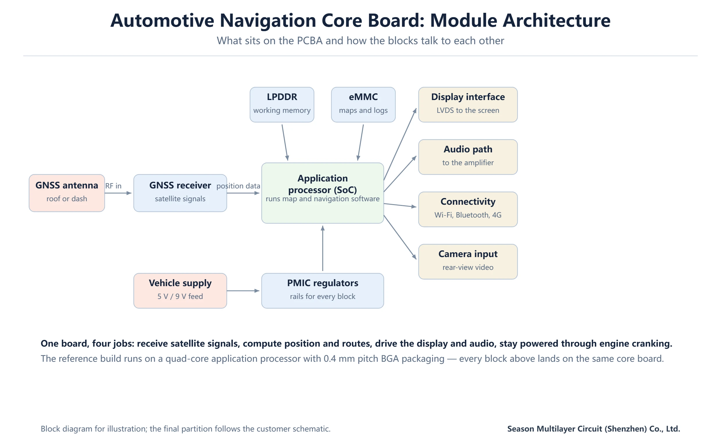
Five functional blocks define the architecture of an automotive navigation PCBA. The signal path starts at the GNSS antenna and ends at the vehicle’s display and speakers:
The reference build in the diagram runs on a quad-core application processor in a 0.4 mm pitch BGA package. Every block around it lands on the same core board, which is why the assembly line capability matters as much as the schematic: a module architecture is only as good as the factory’s ability to place and inspect its densest packages.
Hardware Building Blocks and Their Roles
Each block has a defined job and a layout constraint that follows from it:
| Block | Function | Design note |
|---|---|---|
| GNSS receiver | Down-converts and decodes satellite signals into position data | Sensitive RF front end needs a clean ground and short antenna feed |
| Application processor | Runs the map and navigation software | Fine-pitch BGA defines the assembly and inspection limits |
| LPDDR memory | Working memory for the navigation stack | Trace lengths tuned between memory and processor |
| eMMC storage | Holds map data and system logs | Soldered, not socketed, so vibration cannot walk it out |
| PMIC regulators | Turn the vehicle supply into stable rails | Must ride through engine cranking dips |
| Connectivity module | Wi-Fi, Bluetooth or cellular link | Antenna area kept clear of noisy power rails |
| Display and audio interfaces | LVDS video out, audio path to the amplifier | Differential pairs referenced to solid planes |
Two blocks deserve buyer attention. The GNSS receiver’s performance depends on layout discipline around the antenna feed — a cheap receiver on a clean board beats a premium receiver on a noisy one. And the PMIC section, often treated as an afterthought, is what keeps the module alive during cranking when the vehicle supply sags; its input network and regulator selection should be reviewed for the actual voltage range the installation will see.
Assembly Capability Limits: 0201 Parts and 0.4 mm BGA
A navigation core board concentrates the hardest SMT work on one panel. The reference production window looks like this:
| Parameter | Capability |
|---|---|
| Smallest passive package | 0201 |
| Minimum BGA pitch | 0.4 mm |
| Minimum BGA ball diameter | 0.2 mm |
| Panel size range | 50 × 30 mm to 510 × 460 mm |
| Base material | FR-4, Tg 170 grade, 1.6 mm typical |
| Component packages | SOP, SOT, QFN, QFP, BGA |
What does that mean in practice? The 0.4 mm pitch BGA is the binding constraint: at that pitch, the solder paste volume on each pad is small enough that stencil design, placement accuracy and reflow profile all have to hold together. The 0201 passives crowding the processor’s power pins need the same discipline. If your supplier’s quoted capability is coarser than the packages your schematic actually uses, the gap will show up as placement defects — not as a design problem you can fix in software.
How Automotive Navigation PCBA Is Assembled and Tested
Assembly follows the standard SMT sequence, but each step has a navigation-specific reason:
- Solder paste printing — a stainless stencil deposits paste on every pad, including the 0201 footprints where volume tolerance is tightest.
- Pick and place — high-speed mounters place 0201 chips and fine-pitch ICs; the 0.4 mm pitch BGA is placed with vision alignment.
- Reflow soldering — the oven profile follows the paste specification so both the tiny passives and the large BGA reach proper joint formation.
- AOI — optical inspection checks placement, polarity and solder joints on every panel right after reflow.
- X-ray sampling — BGA joints hide under the package, so X-ray checks for voids, bridging and missing balls.
- Functional test — a power-on test confirms GNSS lock, display output and audio paths before packing.
Most core boards are populated on both faces, which adds a second print-place-reflow cycle. The second side’s components hang upside down during its reflow, so heavier parts are assigned to the first side and the reflow profile is tuned so second-side joints do not collapse. It is routine work for an experienced line, but it is exactly where a line without volume history on 0.4 mm BGA starts to drift.
Reliability Checks for Cabin Electronics
A dashboard module lives with temperature swings, constant vibration and supply transients. The factory-side answer is layered: material selection first — a Tg 170 FR-4 grade keeps the laminate stable through reflow and under dashboard heat — then process controls such as solder paste inspection and AOI on every panel, X-ray sampling on BGA lots, and functional testing that exercises the interfaces rather than just checking for power-on.
Workmanship criteria give those inspections a defined line between accept and reject. Electronics assembly workmanship is judged against the IPC acceptance standards family, and agreeing the applicable class up front prevents the classic dispute where a joint one party calls cosmetic passes as a defect the next day.
Production system certification matters as much as any single test. Lines certified to ISO 9001:2015 give you process discipline, and IATF 16949 certified automotive lines add the traceability and change-control discipline vehicle programs expect. When you audit a supplier for an automotive navigation PCBA, ask which lines the board will actually run on — the certificate should match the production floor, not just the company.
How to Qualify a Navigation PCBA Supplier
The qualification question is not “can you assemble BGA?” but “can you show me?”. A practical scorecard:
| Check | What a good answer looks like |
|---|---|
| Assembly capability | Documented 0201 and 0.4 mm pitch BGA track record, with placement accuracy figures |
| Inspection | AOI on every panel, X-ray sampling on every BGA lot, retention samples kept |
| Quality system | ISO 9001:2015 as the base; IATF 16949 lines for automotive programs |
| Engineering review | DFM and test-point review returned before production, with concrete findings |
| Traceability | Batch records from laminate lot to finished module |
| Turnkey options | PCB fabrication and assembly under one roof, so stackup and stencil decisions are made together |
The full checklist with weighting is in our PCBA assembly supplier selection checklist, and the board-level half of the story — material, stackup and process choices for vehicle electronics — is covered in the automotive electronics PCB guide. Reviewing the two together covers both halves of the BOM.
Data completeness speeds the quote: your Gerber data, BOM with manufacturer part numbers, centroid file and test requirements. Under those conditions, engineering feedback and assembly capability confirmation typically come back within days, not weeks.
How Navigation PCBA Cost Scales
Cost for a navigation core board is driven by structure, not by negotiation alone. The bare board is usually a 4-to-8-layer FR-4 panel — modest by multilayer standards — so the assembly side dominates: the number of fine-pitch packages, the density of 0201 passives, double-sided population, and the test coverage you require. Every additional X-ray inspection lot or functional test station adds process time per panel.
Volume changes the mix. At prototype quantities, setup and stencil costs dominate, so design changes are cheap to absorb; at production volumes, yield on the fine-pitch packages becomes the lever — a percentage point of first-pass yield is worth more than any unit-price concession. That is why we anchor quotations on the cost drivers checklist logic and confirm assembly-specific multipliers per project at engineering review. Related applications — from a 6-layer automotive PCB prototype to a 6-layer HDI rearview mirror PCB — follow the same scaling pattern.
Frequently Asked Questions
What does an automotive navigation core board do?
It receives satellite positioning signals through the GNSS receiver, computes position and routes on the application processor, and drives the map display and voice output through its display and audio interfaces. Because it ships as a complete assembled module, it connects to the vehicle’s screen, amplifier and antenna rather than carrying them on board.
Why is 0.4 mm BGA pitch significant for navigation PCBA?
The application processor and connectivity chips in a navigation module typically come in 0.4 mm pitch BGA packages. At that pitch, paste volume per pad is small and alignment tolerance is tight, so stencil design, placement accuracy and reflow profiling must all be proven. A supplier who routinely handles 0.4 mm pitch BGA with X-ray verification removes the biggest assembly risk on this board type.
What board material is used for automotive navigation modules?
The reference build uses FR-4 at Tg 170 in a 1.6 mm thickness. The higher glass transition point keeps the laminate stable through reflow and under sustained dashboard heat, which matters more in a vehicle than in office electronics. If the installation environment demands more, material upgrades are evaluated at engineering review against the actual temperature profile.
How are hidden BGA solder joints checked?
BGA balls sit under the package, so optical inspection cannot see them. The standard controls are X-ray sampling per production lot to catch voids, bridging and missing balls, plus electrical verification: boundary-scan or functional test confirms every ball landed. For safety-relevant automotive programs, X-ray coverage can be increased beyond sampling by agreement.
What is the difference between a core board and a full head unit?
The core board is the compute module: processor, memory, storage, GNSS receiver, power and connectivity. The head unit adds the enclosure, screen, buttons, amplifier and the vehicle harness interfaces. Making the core board a separate PCBA lets one computing module serve several head-unit models and keeps its fine-pitch assembly under dedicated process control.
Which quality checks matter most for cabin PCBA?
Four layers of defense: solder paste inspection and AOI on every panel to catch placement and joint defects early, X-ray sampling on BGA lots because those joints are invisible, functional testing that exercises GNSS lock, display and audio paths, and a certified quality system — ISO 9001:2015 as the base, with IATF 16949 lines for automotive programs.
What files does a supplier need to quote a navigation PCBA?
Gerber data for the bare board, a BOM with manufacturer part numbers, a centroid (pick-and-place) file, and your test requirements. With those four, a factory can confirm assembly capability against the finest packages in the BOM, return engineering feedback, and quote both fabrication and turnkey assembly. Schematic and layout files can follow at engineering review.
Get Your Navigation Core Board PCBA Reviewed
Send your Gerber files, BOM and test requirements, and our engineering team will confirm assembly capability against your finest-pitch packages, flag DFM risks on the 0.4 mm pitch BGA zones, and return a fabrication-plus-assembly plan with a realistic schedule.
For the bare-board side of the project, start from the PCB manufacturing services overview, or see how the assembly line works end to end in the PCB manufacturing process guide.