Book Appointment Now

A practical PCB reliability testing matrix: electrical, thermal cycling, humidity, mechanical and cleanliness tests, with acceptance criteria for your PO.
PCB Reliability Testing: Test Matrix, Methods and Acceptance
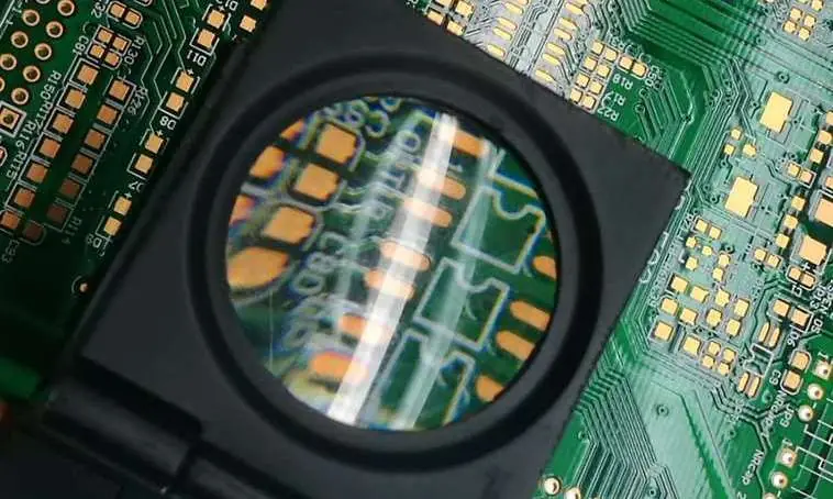
Most reliability problems are decided long before the first field failure: they were designed into the stackup, or left in by a process step nobody asked about. PCB reliability testing is how a buyer converts a supplier’s promises into measured evidence — but only if the test plan matches the product’s real use environment and the acceptance criteria are written down before production starts.
This guide lays out a working test matrix organized the way factories actually run it: electrical screening, environmental stress, mechanical integrity and cleanliness, plus the material verification and failure-analysis steps that close the loop. Each section notes what the test proves, where its limits are, and what a reasonable acceptance line looks like, so you can adapt the matrix to your own qualification plan.
Table of Contents
- What PCB Reliability Testing Can and Cannot Prove
- Build the Test Plan From the Use Environment
- Electrical Tests: Continuity, Insulation and Withstanding Voltage
- Thermal Cycling: What -40 to +125 °C Cycles Reveal
- Humidity, CAF and Ionic Cleanliness Tests
- Mechanical Tests: Vibration, Bend and Peel Strength
- Material Verification: Tg, CTE and Laminate Data
- PCB Reliability Testing on HDI Boards: What Changes
- Reading Failure Analysis Results: Cross-Sections to SEM
- How to Write Acceptance Criteria Into Your Purchase Order
- Put a Test Plan Behind Your Next Build
- FAQ
- Get a Qualification Plan With Your Quote
What PCB Reliability Testing Can and Cannot Prove
A reliability test answers one question at a time. Continuity and insulation testing prove that the board as manufactured is electrically sound. Thermal cycling proves that vias, pads and plated interfaces survive repeated expansion and contraction. Neither proves the board will run for ten years in your enclosure — reliability is inferred from stress models, not measured directly on a two-week project timeline.
That is why a test plan has two jobs. First, catch manufacturing escapes: latent defects such as thin plating in high-aspect-ratio holes, marginal adhesion, or contamination that would otherwise surface during assembly or early service. Second, build a baseline: when you later change a laminate, a finish or a fabricator, re-running the same matrix tells you whether the change moved the needle. The value is less in any single number than in comparable numbers over time.
The framework underneath most acceptance limits is IPC qualification standards, principally IPC-6012 for rigid board performance and IPC-TM-650 for test methods. If you anchor your purchase order to these references, both sides measure the same thing the same way.
Build the Test Plan From the Use Environment
Testing everything at the harshest level wastes money; testing nothing qualifies nothing. The practical starting point is a short description of where the product lives: its operating temperature range, humidity exposure, vibration source, expected service life and rework expectations. From that profile, a sensible matrix falls out — an indoor gateway board and a motor-drive control board share many tests but differ sharply in thermal cycling depth and mechanical stress levels.
| Use profile | Tests that matter most | Typical stress level |
|---|---|---|
| Climate-controlled indoor electronics | Electrical screening, solderability, ionic cleanliness | Thermal cycling limited to assembly reflow exposure |
| Industrial equipment, extended temperature | Thermal cycling, insulation resistance, peel strength | Cycling from roughly -40 °C to +125 °C |
| High-vibration or transport-exposed products | Vibration, mechanical shock, bend testing | Sine and random profiles per agreed method |
| Humid or coastal deployments | Humidity bias, CAF resistance, salt fog (if specified) | 85% RH at 40–85 °C depending on the product |
| High-layer-count and HDI builds | Microvia cross-sections, IST-style current cycling, impedance retention | Coupon-based, per design review |
Our automotive electronics PCB guide shows how an extended-temperature stackup and process plan grow out of the same environment-first logic — the standard itself matters less than the temperature range and lifetime the board must survive.
Electrical Tests: Continuity, Insulation and Withstanding Voltage
Electrical screening is the one test class that runs on 100% of production boards. Continuity testing applies a current to every net and confirms low, stable resistance; insulation resistance testing applies a DC voltage between nets and planes and measures leakage, which must stay in the megohm range for a sound board. Together they catch opens, shorts and the conductive residue that flying-probe or bed-of-nails fixtures expose better than any visual check.
| Electrical test | What it verifies | Typical acceptance |
|---|---|---|
| Continuity / net resistance | Every net conducts with low, stable resistance | Within agreed resistance ceiling; no intermittent opens |
| Insulation resistance | Nets, planes and layers stay isolated | Megohm-level resistance at specified DC bias |
| Dielectric withstanding voltage | Insulation survives transient over-voltage | No breakdown or flashover at agreed test voltage and dwell |
| Impedance verification | Controlled-impedance nets meet design targets | Single-ended typically ±10%; ±8% or ±5% on reviewed designs |
Impedance sits at the boundary between electrical screening and design verification. It is measured on the production coupon with a TDR, not inferred from design files, and the tolerance band is a purchasing decision: tighter windows cost more because they constrain the etch and lamination processes. Our impedance measurement guide details how coupons, TDR and VNA methods divide that work.
Thermal Cycling: What -40 to +125 °C Cycles Reveal
Thermal cycling is the workhorse environmental test for rigid boards. Samples move repeatedly between extremes — commonly -40 °C to +125 °C for industrial-grade builds — with dwell times and ramp rates fixed by the agreed method. Every material in the stackup expands at a different rate, so each cycle mechanically works the interfaces: plated hole barrels, blind and buried via joints, and the copper-to-laminate bonds that peel strength testing probes in a single static pull.
Failure modes show up in a predictable order. Weak hole plating develops barrel cracks first, visible as increased resistance in daisy-chain monitoring; marginal pad adhesion produces lifted pads or solder-joint cracking after assembly; resin-FR-4 interfaces with poor cure stability show measurable expansion drift. The accepted pass criterion is functional: after the agreed cycle count, daisy-chain resistance must remain within its defined band, with no cracking observed under cross-section review of the cycle coupons.
Coupon design decides how much information the test returns. A well-built qualification panel carries daisy-chain via structures of the smallest and largest drilled holes in the design, plus press-fit and thermal-relief geometries where used. Without those structures, a cycling test only proves that the easy holes survived.
Humidity, CAF and Ionic Cleanliness Tests
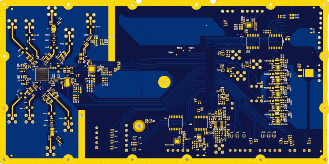
Moisture is the quietest reliability threat. Humidity testing holds boards at elevated temperature and relative humidity — a common screen is 85% RH with bias applied — then re-checks insulation resistance and inspects for corrosion, delamination and leakage-current growth. For dense designs with tight via-to-via spacing, conductive anodic filament (CAF) growth along glass-resin interfaces is the specific mechanism to stress: a biased humidity exposure followed by insulation-resistance trending exposes susceptibility that dry testing never shows.
Cleanliness is the complementary half. Ionic contamination testing extracts residues with an alcohol-water solution and reads the extract’s conductivity — the ROSE test — while ion chromatography names the specific ions when a limit failure needs a root cause. Residues come from plating chemistry, etch processes and flux; they cause corrosion, dendritic growth under bias, and adhesion problems for conformal coating. Acceptance limits are agreed with the assembler’s flux system, because the same residue level that one process tolerates will blind another’s coating.
Mechanical Tests: Vibration, Bend and Peel Strength
Mechanical testing answers whether the board survives handling, mounting and service vibration. Vibration testing runs swept sine or random profiles across the frequency band the product will see, monitoring for opens, cracked joints and loose features. Shock testing applies a calibrated impact — the transport and drop case — and bend testing loads the board to reveal how much curvature the design tolerates before traces or vias fail. Solder-mask and surface-finish durability under these stresses separate robust builds from fragile ones.
Peel strength is the quiet workhorse of the group: it measures the force needed to separate a copper trace from the laminate, typically reported per unit width of foil. A sound FR-4 build holds well above 1.0 N/mm after thermal exposure; a falling number points to poor lamination practice, contaminated prepreg, or a laminate approaching its thermal limit. Because it is cheap and fast, peel strength works well as a per-lot coupon test rather than a one-time qualification event.
For designs where warpage already matters — thin boards, heavy copper zones, unbalanced stackups — mechanical testing should start with flatness measurement at temperature, since a warped panel fails assembly long before it fails vibration. Our balanced stackup guide covers the design side of that prevention.
Material Verification: Tg, CTE and Laminate Data
A qualification plan should verify the laminate you actually received, not just the one on the purchase order. Differential scanning calorimetry reads the glass transition temperature — the point where the resin softens and its mechanical properties drop. Operating temperature must stay below Tg with real margin; a Tg 150 FR-4 grade behaves very differently from a Tg 170 FR-4 grade once a board repeatedly approaches its transition during assembly and service.
Thermomechanical analysis measures the coefficient of thermal expansion below and above Tg, plus the delamination time at elevated temperature (the T260 or T288 style screening used for lead-free assembly margin). Decomposition temperature rounds out the picture. Together these numbers explain most cycling and reflow behavior: expansion mismatch drives via stress, and low delamination time shows up as blistering on the first difficult reflow profile rather than in field data years later.
Verification is a two-document exercise. The supplier provides a mill certificate with Tg, CTE and delamination data for the delivered batch; the buyer spot-checks on qualification builds with a DSC or TMA run on a coupon. The PCB materials and laminates guide on this site maps which laminate classes pair with which service temperatures, so the verification step has a design reference to compare against.
PCB Reliability Testing on HDI Boards: What Changes
HDI builds shift the emphasis of the same matrix. Laser microvias with small capture pads concentrate stress at the via-to-target-pad interface, so cross-section review after thermal cycling becomes the primary evidence: a passing HDI coupon must show intact stacked or staggered via chains, no target-pad separation, and continuous plating through every build-up layer. Electrical daisy-chain monitoring through those structures catches degradation before it becomes visible.
Current-cycling methods in the IST family pass controlled current through a dedicated coupon trace, heating the structure repeatedly and tracking resistance over hundreds of cycles — a faster proxy for long-term via fatigue than chamber cycling alone. For an example of how these requirements translate into a real 2-Stage build, see our 10-layer 2-Stage HDI prototype page, which lists the stackup and process controls behind the design.
The practical rule for HDI qualification: agree the coupon design at engineering review, before production, because the standard test panels rarely carry microvia structures representative of a specific stackup.
Reading Failure Analysis Results: Cross-Sections to SEM
When a sample fails, the analysis toolbox decides whether you learn the root cause or just re-measure the symptom. Cross-sectioning is the first cut for anything interface-related: it shows plating thickness, barrel cracks, interfacial contamination and resin recession in one image. SEM adds magnification and elemental readout where the optical image is ambiguous — grain-boundary corrosion on a nickel finish, or a copper-rich smear indicating a drilling artifact.
| Failure symptom | First analysis step | What it distinguishes |
|---|---|---|
| Open net, intermittent | X-ray plus dye-and-pry on suspect vias | Barrel crack vs. pad cratering vs. drilled void |
| Joint lifted cleanly from pad | Cross-section through the joint | Black-pad corrosion vs. insufficient wetting vs. pad adhesion loss |
| Insulation resistance drift | Ion chromatography on extracted residues | Conductive contamination vs. CAF growth vs. moisture uptake |
| Blistering after reflow | TMA / delamination-time check on coupon | Laminate margin vs. moisture in the panel vs. profile damage |
| Warpage or cracked joints | Flatness measurement at temperature | Stackup imbalance vs. process-induced stress |
The discipline that makes analysis useful is documentation: photographs with scale, measured values against the agreed acceptance line, and a statement of which test method produced each number. A failure report without method references cannot be compared across builds or suppliers, which is the entire point of running the matrix.
How to Write Acceptance Criteria Into Your Purchase Order
A test plan only binds a supplier when the PO references it. Three lines do most of the work: which standard and class the build follows (IPC-6012 Class 2 or Class 3, and IPC-A-600 Class 3 workmanship where applicable), which coupon tests run per lot, and what happens when a test fails — re-test, quarantine, or full traceability review.
- Name the standard and acceptance class explicitly; “high quality” is not a specification.
- List per-lot coupon tests (peel strength, microsection, solderability, ionic cleanliness) with the method reference for each.
- State the qualification tests for a first build: thermal cycling count, humidity exposure, and any vibration profile, all with pass criteria.
- Require batch traceability so a failure maps to laminate lots, bath campaigns and process dates.
- Agree the failure disposition route in advance — who receives coupons, who reviews micrographs, and the re-test rule.
Suppliers with mature quality systems will return a documented test plan with the quote. If the response is silence, that silence is itself test data: it tells you reliability will be inspected in rather than built in. Our PCB manufacturing process overview maps where each control point sits in the production flow, which makes those conversations concrete.
Put a Test Plan Behind Your Next Build
Season Multilayer Circuit runs coupon-based process control on every production campaign, with IPC-6012 acceptance and batch traceability across 2–30 layer boards. Submit your Gerber data and use-environment summary through our PCB manufacturing services page, and our engineering team will return a test plan with defined acceptance criteria before the first panel is pressed — including finish options verified to UL recognition requirements where the application calls for it.
Frequently Asked Questions
What is included in PCB reliability testing?
A complete program covers four groups: electrical screening (continuity, insulation resistance, withstanding voltage, impedance verification on coupons), environmental stress (thermal cycling, humidity with bias, CAF and salt-fog exposure where specified), mechanical integrity (vibration, shock, bend and peel strength), and cleanliness (ionic contamination testing). Material verification of Tg and CTE closes the loop on what was actually received.
How many thermal cycles should a PCB survive?
It depends on the use profile. Industrial-grade builds are commonly screened at roughly 500 to 1,000 cycles between -40 °C and +125 °C on daisy-chain coupons, with resistance required to stay within its defined band. Consumer products may need far fewer cycles; long-service industrial equipment may be qualified beyond that. The cycle count should be derived from the product’s expected lifetime temperature history, not copied from another project.
What is the difference between IPC Class 2 and Class 3 acceptance?
Class 2 covers general electronics where continued function is expected but interruption is tolerable; Class 3 adds tighter acceptance on plating thickness, annular ring registration, dielectric spacing and workmanship details under IPC-A-600 and IPC-6012. Class 3 boards cost more because the tighter limits reduce process latitude, so the class should follow the consequence of failure in your product, not ambition.
How is reliability verified on HDI boards?
Through coupon structures that carry the actual microvia geometries: daisy-chained blind and buried vias cycled electrically or thermally, followed by cross-section review of the via chains after stress. Current-cycling methods in the IST family provide a faster proxy for via fatigue. The coupon design must be agreed at engineering review so it represents the specific stackup being bought.
What does 100% electrical testing cover before shipment?
Flying-probe or bed-of-nails testing verifies continuity and insulation on every net against the netlist: no opens, no shorts, and leakage within limits. It runs on all production boards. Impedance verification, by contrast, is measured on coupons, and environmental or mechanical qualification applies to sampled or dedicated test pieces.
Which documents should a supplier provide with reliability data?
At minimum: a test report naming the method standard for each test, measured values against the agreed acceptance line, mill certificates for the laminate batch (Tg, CTE, delamination time), and traceability linking coupons to production lots and bath campaigns. Reports without method references cannot be compared across builds, which defeats the purpose.
How do I build a test plan for a new product?
Start from the use environment: temperature range, humidity, vibration, service life and rework expectations. Select the heaviest tests that match those exposures, anchor acceptance to IPC-6012 and IPC-TM-650 references, define coupon structures at engineering review, and write the whole plan into the purchase order so it binds before production rather than after a failure.
Get a Qualification Plan With Your Quote
Send your Gerber files and use-environment notes to Season Multilayer Circuit, and our engineers will return a coupon and test plan with written acceptance criteria alongside the quote. Start at the manufacturing services page, or review our 6-layer automotive PCB prototype page for an example of extended-temperature qualification in practice.